Design & Selection · Module 02
Cameras: monocular, stereo, RGB-D, event, thermal, shutter type
Five camera types answer different questions. Pick by the failure you must survive: darkness, sunlight, texture-less walls or fast motion.
Assumptions: Class-level tendencies of each sensor type, not product specifications. Ratings (good, degraded, poor) and classes (range, accuracy, rate) are coarse and exist to flag obvious mismatches; the datasheet and your own tests decide. Exception: the “Real-World Camera Products” section quotes manufacturer specifications that were read from each manufacturer’s own page on 2026-11-06, with the unit, condition, source link and date beside every figure; nothing there is estimated, and a figure that could not be attributed to one model reliably is left out.
1. Engineering problem
Cameras give rich information cheaply, but they differ on whether they provide depth, whether they work in sunlight or darkness, and how much compute they need. The shutter type decides how fast motion distorts an image.
Global versus rolling shutter
A global shutter exposes every pixel at the same time, so a fast-moving or rotating camera produces an undistorted image. A rolling shutter exposes row by row, so fast motion skews the image and breaks the assumption of most visual-odometry and calibration pipelines that every pixel shares one pose. For fast platforms (UAVs, legged robots, vehicles) prefer a global shutter or model the rolling shutter in the estimator; rolling shutters are cheaper and fine for slow robots.
Jump to the working principles with animations and videos, or to the product explorer.
2. When is this needed?
- Choosing a sensor type for a new robot, or a replacement when one fails to meet a requirement.
- Explaining to a team why a sensor behaves differently in the field than on the bench.
- Writing the datasheet checklist before you buy.
3. Selection and design decisions
| Sensor type | Typical range class | Accuracy class | Rate class | Compute | Power | Cost |
|---|---|---|---|---|---|---|
| Monocular camera | n/a | not a distance sensor | about 10s to 100 Hz | medium | very low | very low |
| Stereo camera | tens of metres | decimetre class | about 10s to 100 Hz | high | low | low |
| RGB-D (active depth) camera | metres (up to ~10 m class) | centimetre class | about 10s to 100 Hz | medium | low | low |
| Event camera | n/a | not a distance sensor | about 100 Hz and above | medium | very low | high |
| Thermal (long-wave infrared) camera | n/a | not a distance sensor | about 10s to 100 Hz | medium | low | high |
| Sensor type | darkness | direct sunlight | fog or smoke | rain or spray | dust | glass and mirrors |
|---|---|---|---|---|---|---|
| Monocular camera | poor | degraded | poor | degraded | degraded | degraded |
| Stereo camera | poor | degraded | poor | degraded | degraded | poor |
| RGB-D (active depth) camera | good | poor | poor | poor | degraded | poor |
| Event camera | degraded | good | poor | degraded | degraded | degraded |
| Thermal (long-wave infrared) camera | good | good | degraded | degraded | good | poor |
Every sensor type below follows the same 18-point template, from what it measures to the alternatives. Use the interactive Sensor Comparison Tool to compare any of them side by side.
Working principle at a glance, with videos to watch
About the videos. Each link was confirmed to be a real YouTube video (title and channel as YouTube reports them, checked 2026-11-06). I could not watch them or read their captions, so I only say what the title and channel support; check that a video suits you before relying on it. Several are made by camera manufacturers, who explain their own approach favourably. The links open YouTube; nothing is embedded, so no YouTube content loads on this page.
Monocular camera (the pinhole model)
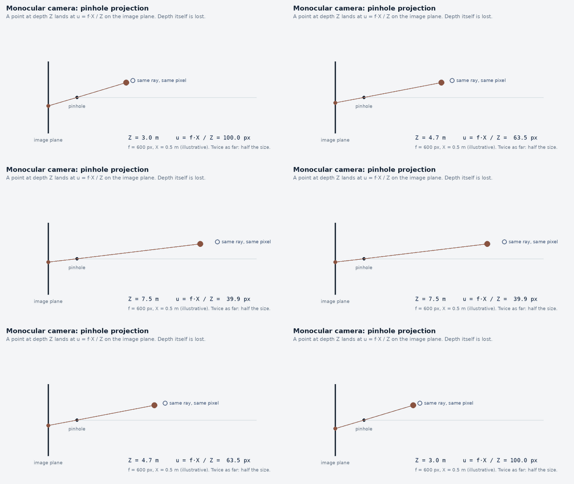
- Camera Intrinsics and Extrinsics - 5 Minutes with Cyrill · Cyrill Stachniss · 5:59 (a university lecturer’s short explanation of the camera model)
Shutter: global versus rolling
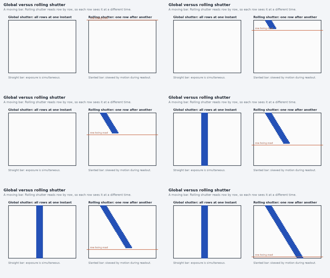
- Global Shutter vs. Rolling Shutter · Sony · 0:33 (by a sensor manufacturer: a short demonstration)
- What is Global Shutter? (And How Does It Work?) · B&H Photo Video Pro Audio · 1:10 (by a retailer, aimed at photographers and videographers)
Stereo depth camera
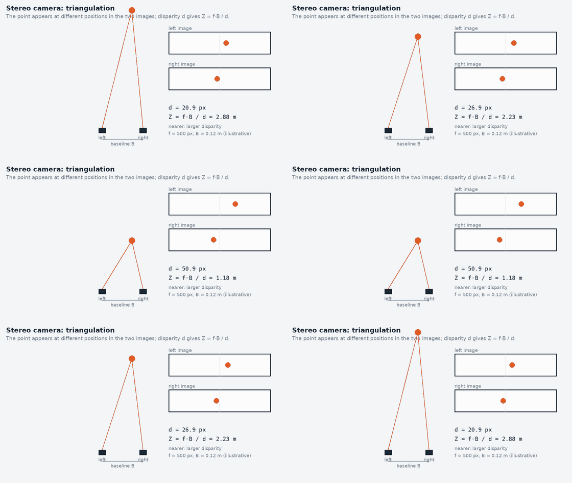
- Depth Camera - Computerphile · Computerphile · 12:34 (a general-audience explanation)
- Simple Stereo | Camera Calibration | First Principles of Computer Vision · First Principles of Computer Vision · 16:34 (a lecture-style course video)
- Intel® RealSense™ Depth Cameras D415 & D435 · RealSense · 1:19 (by the manufacturer: a short product overview)
The last video is a manufacturer’s overview of two stereo products; the middle one is a lecture on stereo geometry.
Structured-light depth camera
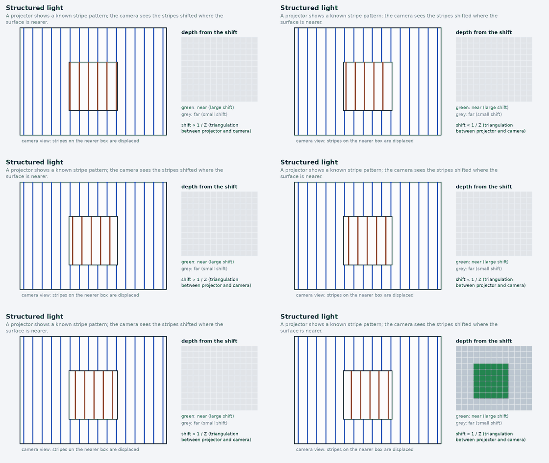
- Structured Light Range Finding | Active Illumination Methods | First Principles of Computer Vision · First Principles of Computer Vision · 24:23 (a lecture-style course video)
- Structured Light · Udacity · 2:09 (a short course clip)
- Time-of-Flight (ToF) vs Stereo Vision vs Structured light – Detailed look | eVision Hub - Ep 09 | e-con Systems · e-con Systems · 3:09 (by a camera maker comparing the three depth methods; not neutral about its own products)
The last video compares time of flight, stereo and structured light, per its title.
Time-of-flight (ToF) camera
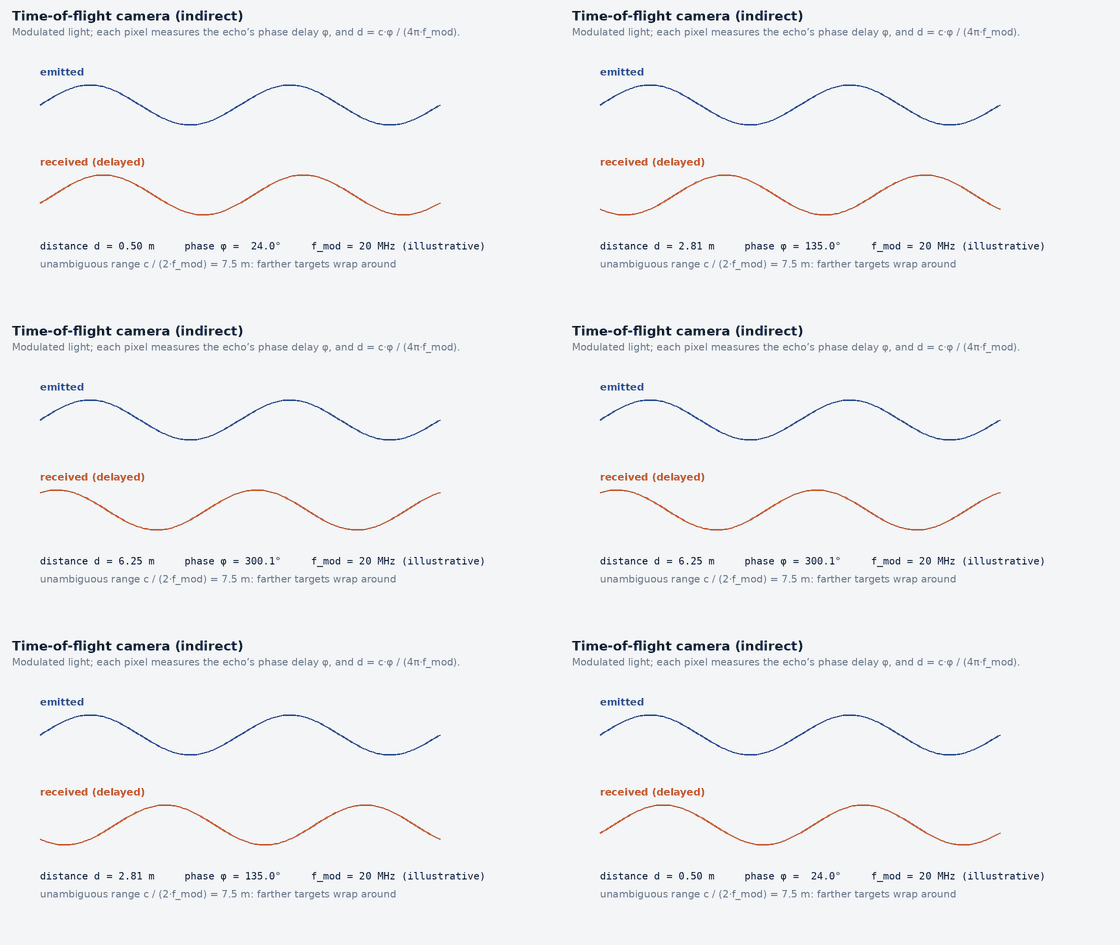
- WHAT IS ToF? All About Time-of-Flight and the FRAMOS ToF Devkit · FRAMOS · 3:42 (by a camera-components distributor, with a product demo)
- How ToF(Time of Flight) Cameras Work: Principles and Advantages of Time-of-Flight 3D Depth Camera · ToF Depth 3D Camera_CubeEye · 3:02 (by a ToF-camera maker)
- What is 3D Time-of-Flight? ToF Cameras Ultimate Guide! · Goermicro Vzense Technology,Inc. · 7:47 (by a ToF-camera maker)
Two of these are by ToF camera makers, and one by a components distributor.
Event camera (neuromorphic)
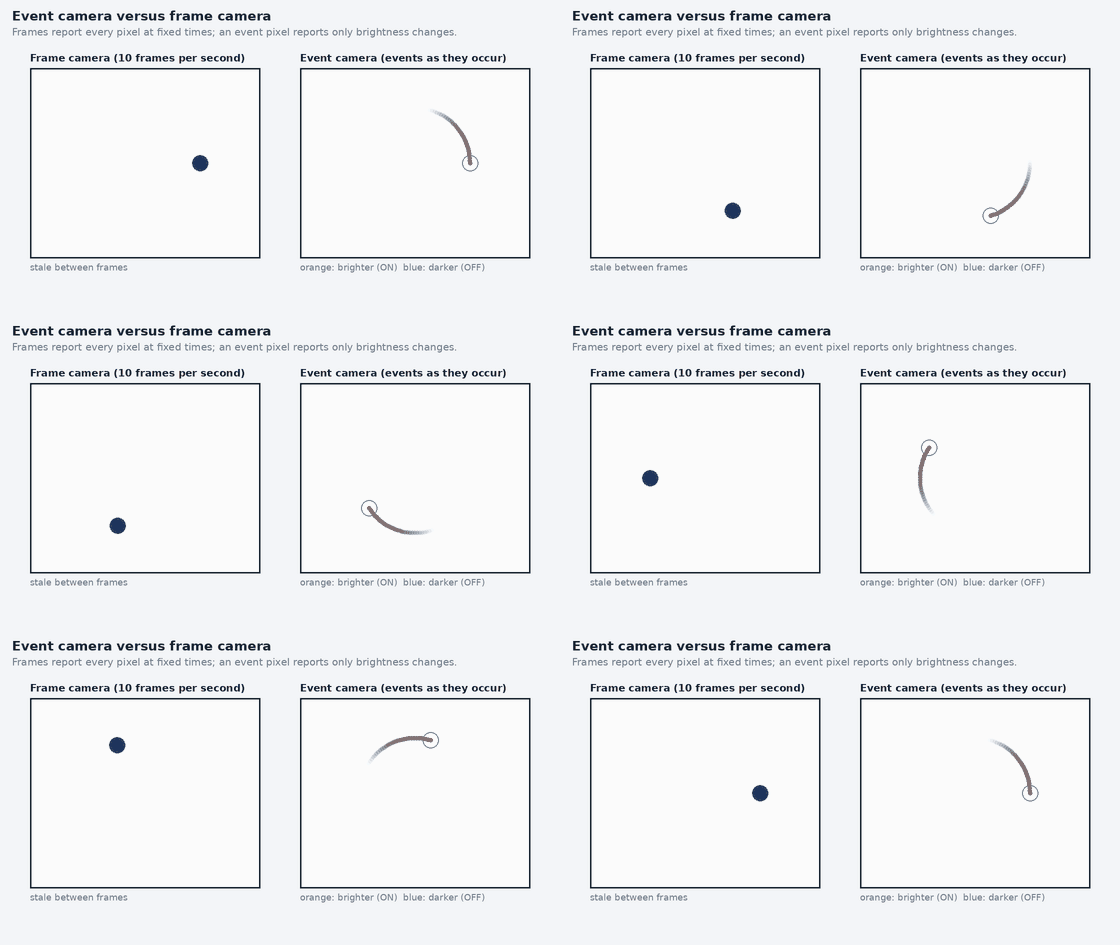
- What is Event-Based Vision | Metavision by Prophesee · PROPHESEE · 3:42 (by an event-sensor maker, so it favours event cameras)
- Event Cameras: a New Way of Sensing - Davide Scaramuzza - ICCP 2024 Keynote · UZH Robotics and Perception Group · 1:06:24 (a long research keynote from a robotics research group)
- Rocket launch from a Neuromorphic Camera - Events vs. Frames · International Centre for Neuromorphic Systems · 0:50 (a short side-by-side demonstration)
The first is by an event-sensor maker; the second is a research keynote of over an hour; the third is a short demonstration.
Thermal camera
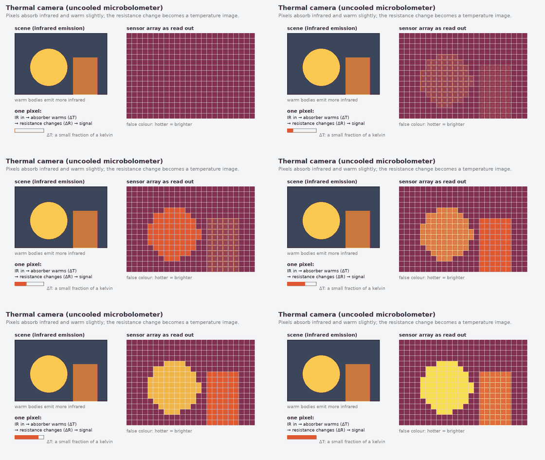
- What's the difference between cooled & uncooled thermal detectors? · Teledyne FLIR · 2:22 (by a thermal-camera maker)
- Ask an Expert: What is a Microbolometer? · Sierra-Olympia Technologies · 3:35 (by a thermal-imaging distributor)
What happens to the images afterwards
- SLAM - 5 Minutes with Cyrill · Cyrill Stachniss · 5:00 (what is done with the images after they are captured)
Real-World Camera Products and Manufacturer Comparison
Status of this section (read 2026-11-06). Specifications for 9 models (RealSense D435i and D455, Stereolabs ZED 2i, Luxonis OAK-D S2, Orbbec Gemini 335 and Femto Bolt, Prophesee Metavision EVK4, and Basler acA1920-40uc and ace 2 a2A1920-51gcBAS) were read from the manufacturer’s own product or documentation page; each figure below shows its unit, the mode or condition it applies to, and a link to the source with the date read. A figure that could not be attributed to one model reliably (for example a column of a multi-product comparison table) is left out and says so. For the other 2 products no usable manufacturer text was available in this build, so no specification is shown for them: the cards give only the vendor’s general category and a link to the manufacturer’s site. Photographs: the RealSense, Stereolabs, Luxonis and Orbbec cards show the photograph from the manufacturer’s own product page, shown with a credit and a link to that page; the images were saved and resized for this site after the site owner pointed to those pages. Reuse permission for these images has not been verified by this build and should be confirmed with each manufacturer. The other products show a labelled placeholder because no photograph was supplied.
Reading the figures: a manufacturer page states ranges, resolutions and frame rates for modes, not for the camera in general: depth resolution, frame rate and field of view usually trade against each other. Depth accuracy is only meaningful with its distance and conditions (a “1.5 % at 2 m” figure says nothing about 10 m). Event sensors are not frame cameras: their resolution is a pixel count, their “frame rate” is an equivalent time resolution, and their dynamic range comes with footnoted conditions. Everything in these cards is a manufacturer statement; none is independently measured. No product prices are shown.
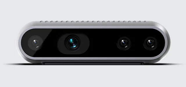
RealSense D435i (D430 series)
Technology: Stereo depth camera (passive or unspecified) (as described in the manufacturer’s documentation)
Stereo depth camera with an integrated IMU. The product page describes the D430 family: stereoscopic depth with global-shutter imagers. Figures below are the series figures on that page; other D400 models differ.
- Depth range
- 0.3 to 3 (ideal range); minimum 0.2 m series-level: the page states an ideal operating range of 0.3 m to 3 m for the D430 family and a minimum depth distance of 20 cm; stereo depth can operate beyond that depending on scene · manufacturer specification page, read 2026-11-06
- Field of view
- 87 × 58 ° depth field of view (horizontal × vertical), D430 series page · manufacturer specification page, read 2026-11-06
- Resolution
- up to 1280 × 720 px depth output resolution, D430 series page · manufacturer specification page, read 2026-11-06
- Frame rate
- up to 90 fps depth frame rate, D430 series page · manufacturer specification page, read 2026-11-06
- Shutter
- global shutter image sensor technology stated for the D430 series · manufacturer specification page, read 2026-11-06
- Stereo baseline
- Not yet verified in this build
- Depth accuracy
- Not yet verified in this build
- Dynamic range
- Not yet verified in this build
- Interface
- Not yet verified in this build
- IMU
- yes the D435i, D435if and D436 include an IMU, per the page · manufacturer specification page, read 2026-11-06
Manufacturer site · Official product page · Specification page
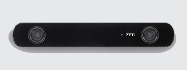
Stereolabs ZED 2i
Technology: Stereo depth camera (passive or unspecified) (as described in the manufacturer’s documentation)
Wide-angle stereo camera in a sealed housing with neural depth. Its page calls it a rolling-shutter camera. The page’s comparison table has one column per product; the column for this model was identified by its baseline row (see the baseline cell), and the depth and field-of-view figures below come from that column.
- Depth range
- 0.3 to 20 (2.1 mm lens); 1.5 to 35 (4 mm lens) m maximum depth range, the ZED 2i column of the comparison table; the same table gives the ideal range as 0.3 to 12 m (2.1 mm lens) and 1.5 to 20 m (4.6 mm lens), and the page names the long lens 4 mm in one row and 4.6 mm in others · manufacturer specification page, read 2026-11-06
- Field of view
- 110 × 70 (2.1 mm lens); 68 × 38 (4.6 mm lens) ° horizontal × vertical field of view (maximum), the ZED 2i column of the comparison table; the page text also states up to 120° diagonal · manufacturer specification page, read 2026-11-06
- Resolution
- 1080p video resolution shown on the product card; other modes exist · manufacturer specification page, read 2026-11-06
- Frame rate
- 100 Hz depth frame rate, “up to 100Hz” in the ZED 2i column; 1080p video is offered at 30 or 15 fps · manufacturer specification page, read 2026-11-06
- Shutter
- rolling shutter page text: “ZED 2i is an IP66-rated Rolling Shutter camera” · manufacturer specification page, read 2026-11-06
- Stereo baseline
- 120 mm stereo baseline shown on the product card · manufacturer specification page, read 2026-11-06
- Depth accuracy
- Not yet verified in this build
- Dynamic range
- Not yet verified in this build
- Interface
- USB 3.1 (Type-C connection) page text · manufacturer specification page, read 2026-11-06
- IMU
- built-in IMU, barometer and magnetometer product card · manufacturer specification page, read 2026-11-06
Manufacturer site · Official product page · Specification page
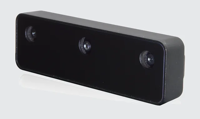
Luxonis OAK-D S2
Technology: Stereo depth camera (passive or unspecified) (as described in the manufacturer’s documentation)
Stereo depth camera with a central colour camera and on-device AI processing. The documentation entry lists no dot projector and no infrared illumination, so depth is from passive stereo.
- Depth range
- Not yet verified in this build
- Field of view
- Not yet verified in this build
- Resolution
- 12 MP central RGB camera, per the entry’s key features · manufacturer specification page, read 2026-11-06
- Frame rate
- Not yet verified in this build
- Shutter
- global shutter the entry’s features field gives shutterType “global” · manufacturer specification page, read 2026-11-06
- Stereo baseline
- 75 mm stereo baseline in the entry · manufacturer specification page, read 2026-11-06
- Depth accuracy
- Not yet verified in this build
- Dynamic range
- Not yet verified in this build
- Interface
- USB-C (USB2 / USB3) connectors and key features in the entry · manufacturer specification page, read 2026-11-06
- IMU
- Not yet verified in this build
Manufacturer site · Official product page · Specification page
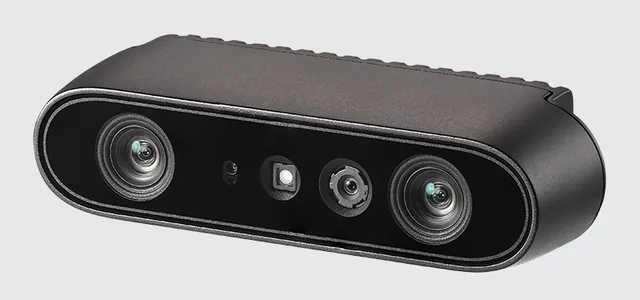
Orbbec Gemini 335
Technology: RGB-D, active infrared stereo (as described in the manufacturer’s documentation)
RGB-D camera using active and passive stereo with a built-in IMU and hardware triggering, positioned for indoor and outdoor robotics.
- Depth range
- 0.10 to 20+ (optimal 0.26 to 3) m depth range as stated on the specification table (Orbbec marks the range with an asterisk) · manufacturer specification page, read 2026-11-06
- Field of view
- 90 × 65 ° depth field of view (horizontal × vertical) · manufacturer specification page, read 2026-11-06
- Resolution
- up to 1280 × 800 px depth resolution at 30 fps · manufacturer specification page, read 2026-11-06
- Frame rate
- up to 30 fps depth at 1280 × 800 · manufacturer specification page, read 2026-11-06
- Shutter
- Not yet verified in this build
- Stereo baseline
- 50 mm stereo baseline · manufacturer specification page, read 2026-11-06
- Depth accuracy
- ≤ 1.5 % RMSE spatial precision at 2 m, 1280 × 800, 90 % × 90 % region of interest · manufacturer specification page, read 2026-11-06
- Dynamic range
- Not yet verified in this build
- Interface
- USB 3.0 Type-C connectivity · manufacturer specification page, read 2026-11-06
- IMU
- built-in the FAQ text and table state an IMU · manufacturer specification page, read 2026-11-06
Manufacturer site · Official product page · Specification page
Orbbec Femto Bolt
Technology: RGB-D, time of flight (as described in the manufacturer’s documentation)
Time-of-flight depth camera with a 4K colour camera and a 6-DoF IMU. Depth mode (wide or narrow field of view) sets the range, resolution and frame rate.
- Depth range
- 0.25 to 5.46 m depending on depth mode (asterisked on the page) · manufacturer specification page, read 2026-11-06
- Field of view
- 120 × 120 (wide) or 75 × 65 (narrow) ° depth field of view, horizontal × vertical, by mode · manufacturer specification page, read 2026-11-06
- Resolution
- up to 1024 × 1024 (wide) or 640 × 576 (narrow) px depth resolution by mode · manufacturer specification page, read 2026-11-06
- Frame rate
- 15 (wide) or 30 (narrow) fps depth at the listed resolutions · manufacturer specification page, read 2026-11-06
- Shutter
- Not yet verified in this build
- Stereo baseline
- Not yet verified in this build
- Depth accuracy
- Not yet verified in this build
- Dynamic range
- Not yet verified in this build
- Interface
- USB Type-C 3.2 page text · manufacturer specification page, read 2026-11-06
- IMU
- 6-DoF IMU page text · manufacturer specification page, read 2026-11-06
Manufacturer site · Official product page · Specification page
Prophesee Metavision EVK4 HD (IMX636)
Technology: Event-based (neuromorphic) vision sensor (as described in the manufacturer’s documentation)
Evaluation kit for the Sony–Prophesee IMX636 event-based vision sensor. It reports per-pixel brightness changes as events, not frames, so its outputs are not images and the usual frame-rate and exposure terms do not apply.
- Depth range
- Not yet verified in this build
- Field of view
- Not yet verified in this build
- Resolution
- 1280 × 720 px event sensor resolution; optical format 1/2.5 inch, pixel size 4.86 µm · manufacturer specification page, read 2026-11-06
- Frame rate
- > 10000 (time resolution equivalent) fps equivalent the page’s “time resolution equivalent”; pixel latency is stated below 100 µs · manufacturer specification page, read 2026-11-06
- Shutter
- Not yet verified in this build
- Stereo baseline
- Not yet verified in this build
- Depth accuracy
- Not yet verified in this build
- Dynamic range
- > 86 / > 120 dB the page gives two values marked with footnotes (* and **) whose conditions were not available in the extracted text; nominal contrast threshold 25 %; low-light cutoff 0.08 lux · manufacturer specification page, read 2026-11-06
- Interface
- Not yet verified in this build
- IMU
- Not yet verified in this build
Manufacturer site · Official product page · Specification page
Basler ace acA1920-40uc
Technology: Monocular, global shutter (machine-vision) (as described in the manufacturer’s documentation)
Global-shutter USB 3.0 machine-vision colour camera with a Sony IMX249 sensor. A typical choice for fast-moving scenes where rolling-shutter skew is not acceptable.
- Depth range
- Not yet verified in this build
- Field of view
- Not yet verified in this build
- Resolution
- 1936 × 1216 (full); 1920 × 1200 (default) px about 2.3 MP; 1/1.2 inch sensor format, pixel size 5.86 × 5.86 µm · manufacturer specification page, read 2026-11-06
- Frame rate
- 41 fps at default settings · manufacturer specification page, read 2026-11-06
- Shutter
- global shutter Sony IMX249LQJ-C progressive-scan CMOS · manufacturer specification page, read 2026-11-06
- Stereo baseline
- Not yet verified in this build
- Depth accuracy
- Not yet verified in this build
- Dynamic range
- Not yet verified in this build
- Interface
- USB 3.0 described as a Basler ace USB 3.0 camera · manufacturer specification page, read 2026-11-06
- IMU
- Not yet verified in this build
Manufacturer site · Official product page · Specification page
Teledyne FLIR Boson series
Technology: Thermal (long-wave infrared) camera (category from the manufacturer’s general positioning; not verified against its documentation in this build)
Uncooled long-wave-infrared thermal camera cores for OEM integration. The exact model sets resolution, field of view and frame rate.
- Depth range
- Not yet verified in this build
- Field of view
- Not yet verified in this build
- Resolution
- Not yet verified in this build
- Frame rate
- Not yet verified in this build
- Shutter
- Not yet verified in this build
- Stereo baseline
- Not yet verified in this build
- Depth accuracy
- Not yet verified in this build
- Dynamic range
- Not yet verified in this build
- Interface
- Not yet verified in this build
- IMU
- Not yet verified in this build
Manufacturer site · Product page: link not verified · Datasheet: link not verified
iniVation DVXplorer
Technology: Event-based (neuromorphic) vision sensor (category from the manufacturer’s general positioning; not verified against its documentation in this build)
Event-based vision sensor camera for research and industrial high-speed sensing.
- Depth range
- Not yet verified in this build
- Field of view
- Not yet verified in this build
- Resolution
- Not yet verified in this build
- Frame rate
- Not yet verified in this build
- Shutter
- Not yet verified in this build
- Stereo baseline
- Not yet verified in this build
- Depth accuracy
- Not yet verified in this build
- Dynamic range
- Not yet verified in this build
- Interface
- Not yet verified in this build
- IMU
- Not yet verified in this build
Manufacturer site · Product page: link not verified · Datasheet: link not verified
Basler ace 2 a2A1920-51gcBAS
Technology: Monocular, global shutter (machine-vision) (as described in the manufacturer’s documentation)
Compact global-shutter colour area-scan camera from Basler’s ace 2 family, with a Sony IMX392 sensor. Other ace 2 models differ in sensor, shutter type and interface: take them from the exact model’s documentation.
- Depth range
- Not yet verified in this build
- Field of view
- Not yet verified in this build
- Resolution
- 1936 × 1216 (full); 1920 × 1200 (default) px about 2.3 MP; Sony IMX392LQR-C, 1/2.3 inch sensor format, pixel size 3.45 × 3.45 µm · manufacturer specification page, read 2026-11-06
- Frame rate
- 51 fps at default settings · manufacturer specification page, read 2026-11-06
- Shutter
- global shutter Sony IMX392LQR-C progressive-scan CMOS · manufacturer specification page, read 2026-11-06
- Stereo baseline
- Not yet verified in this build
- Depth accuracy
- Not yet verified in this build
- Dynamic range
- Not yet verified in this build
- Interface
- Not yet verified in this build
- IMU
- Not yet verified in this build
Manufacturer site · Official product page · Specification page
RealSense D455 (D450 series)
Technology: Stereo depth camera (passive or unspecified) (as described in the manufacturer’s documentation)
Longer-baseline member of the RealSense D400 family for mobile robots and spatial awareness. Figures below are the D450-series figures on the family page; configurations (D455, D455f, D456, D457) differ in IMU, IR-pass filter, enclosure and interface.
- Depth range
- 0.6 to 6 (ideal range) m series-level ideal range on the D450 family page · manufacturer specification page, read 2026-11-06
- Field of view
- 87 × 58 ° depth field of view (horizontal × vertical), D450 series page · manufacturer specification page, read 2026-11-06
- Resolution
- up to 1280 × 720 px depth output resolution · manufacturer specification page, read 2026-11-06
- Frame rate
- up to 90 fps depth frame rate · manufacturer specification page, read 2026-11-06
- Shutter
- global shutter image sensor technology stated for the D450 series · manufacturer specification page, read 2026-11-06
- Stereo baseline
- Not yet verified in this build
- Depth accuracy
- < 2 % depth accuracy at 4 m, D450 series page · manufacturer specification page, read 2026-11-06
- Dynamic range
- Not yet verified in this build
- Interface
- Not yet verified in this build
- IMU
- D455, D455f, D456 and D457 include an IMU configuration table on the page · manufacturer specification page, read 2026-11-06
Manufacturer site · Official product page · Specification page
Manufacturer comparison table
Grouped by technology so that different methods are not compared as if equivalent. The condition under each value says what it applies to. Cells that read “Not yet verified” have no usable manufacturer source in this build.
| Technology | Manufacturer | Model | Depth range | Field of view | Resolution | Frame rate | Shutter | Interface | Source |
|---|---|---|---|---|---|---|---|---|---|
| Monocular, global shutter (machine-vision) | Basler | ace acA1920-40uc | Not yet verified in this build | Not yet verified in this build | 1936 × 1216 (full); 1920 × 1200 (default) px about 2.3 MP; 1/1.2 inch sensor format, pixel size 5.86 × 5.86 µm · manufacturer specification page, read 2026-11-06 | 41 fps at default settings · manufacturer specification page, read 2026-11-06 | global shutter Sony IMX249LQJ-C progressive-scan CMOS · manufacturer specification page, read 2026-11-06 | USB 3.0 described as a Basler ace USB 3.0 camera · manufacturer specification page, read 2026-11-06 | spec page |
| Monocular, global shutter (machine-vision) | Basler | ace 2 a2A1920-51gcBAS | Not yet verified in this build | Not yet verified in this build | 1936 × 1216 (full); 1920 × 1200 (default) px about 2.3 MP; Sony IMX392LQR-C, 1/2.3 inch sensor format, pixel size 3.45 × 3.45 µm · manufacturer specification page, read 2026-11-06 | 51 fps at default settings · manufacturer specification page, read 2026-11-06 | global shutter Sony IMX392LQR-C progressive-scan CMOS · manufacturer specification page, read 2026-11-06 | Not yet verified in this build | spec page |
| Stereo depth camera (passive or unspecified) | RealSense | D435i (D430 series) | 0.3 to 3 (ideal range); minimum 0.2 m series-level: the page states an ideal operating range of 0.3 m to 3 m for the D430 family and a minimum depth distance of 20 cm; stereo depth can operate beyond that depending on scene · manufacturer specification page, read 2026-11-06 | 87 × 58 ° depth field of view (horizontal × vertical), D430 series page · manufacturer specification page, read 2026-11-06 | up to 1280 × 720 px depth output resolution, D430 series page · manufacturer specification page, read 2026-11-06 | up to 90 fps depth frame rate, D430 series page · manufacturer specification page, read 2026-11-06 | global shutter image sensor technology stated for the D430 series · manufacturer specification page, read 2026-11-06 | Not yet verified in this build | spec page |
| Stereo depth camera (passive or unspecified) | Stereolabs | ZED 2i | 0.3 to 20 (2.1 mm lens); 1.5 to 35 (4 mm lens) m maximum depth range, the ZED 2i column of the comparison table; the same table gives the ideal range as 0.3 to 12 m (2.1 mm lens) and 1.5 to 20 m (4.6 mm lens), and the page names the long lens 4 mm in one row and 4.6 mm in others · manufacturer specification page, read 2026-11-06 | 110 × 70 (2.1 mm lens); 68 × 38 (4.6 mm lens) ° horizontal × vertical field of view (maximum), the ZED 2i column of the comparison table; the page text also states up to 120° diagonal · manufacturer specification page, read 2026-11-06 | 1080p video resolution shown on the product card; other modes exist · manufacturer specification page, read 2026-11-06 | 100 Hz depth frame rate, “up to 100Hz” in the ZED 2i column; 1080p video is offered at 30 or 15 fps · manufacturer specification page, read 2026-11-06 | rolling shutter page text: “ZED 2i is an IP66-rated Rolling Shutter camera” · manufacturer specification page, read 2026-11-06 | USB 3.1 (Type-C connection) page text · manufacturer specification page, read 2026-11-06 | spec page |
| Stereo depth camera (passive or unspecified) | Luxonis | OAK-D S2 | Not yet verified in this build | Not yet verified in this build | 12 MP central RGB camera, per the entry’s key features · manufacturer specification page, read 2026-11-06 | Not yet verified in this build | global shutter the entry’s features field gives shutterType “global” · manufacturer specification page, read 2026-11-06 | USB-C (USB2 / USB3) connectors and key features in the entry · manufacturer specification page, read 2026-11-06 | spec page |
| Stereo depth camera (passive or unspecified) | RealSense | D455 (D450 series) | 0.6 to 6 (ideal range) m series-level ideal range on the D450 family page · manufacturer specification page, read 2026-11-06 | 87 × 58 ° depth field of view (horizontal × vertical), D450 series page · manufacturer specification page, read 2026-11-06 | up to 1280 × 720 px depth output resolution · manufacturer specification page, read 2026-11-06 | up to 90 fps depth frame rate · manufacturer specification page, read 2026-11-06 | global shutter image sensor technology stated for the D450 series · manufacturer specification page, read 2026-11-06 | Not yet verified in this build | spec page |
| RGB-D, active infrared stereo | Orbbec | Gemini 335 | 0.10 to 20+ (optimal 0.26 to 3) m depth range as stated on the specification table (Orbbec marks the range with an asterisk) · manufacturer specification page, read 2026-11-06 | 90 × 65 ° depth field of view (horizontal × vertical) · manufacturer specification page, read 2026-11-06 | up to 1280 × 800 px depth resolution at 30 fps · manufacturer specification page, read 2026-11-06 | up to 30 fps depth at 1280 × 800 · manufacturer specification page, read 2026-11-06 | Not yet verified in this build | USB 3.0 Type-C connectivity · manufacturer specification page, read 2026-11-06 | spec page |
| RGB-D, time of flight | Orbbec | Femto Bolt | 0.25 to 5.46 m depending on depth mode (asterisked on the page) · manufacturer specification page, read 2026-11-06 | 120 × 120 (wide) or 75 × 65 (narrow) ° depth field of view, horizontal × vertical, by mode · manufacturer specification page, read 2026-11-06 | up to 1024 × 1024 (wide) or 640 × 576 (narrow) px depth resolution by mode · manufacturer specification page, read 2026-11-06 | 15 (wide) or 30 (narrow) fps depth at the listed resolutions · manufacturer specification page, read 2026-11-06 | Not yet verified in this build | USB Type-C 3.2 page text · manufacturer specification page, read 2026-11-06 | spec page |
| Event-based (neuromorphic) vision sensor | Prophesee | Metavision EVK4 HD (IMX636) | Not yet verified in this build | Not yet verified in this build | 1280 × 720 px event sensor resolution; optical format 1/2.5 inch, pixel size 4.86 µm · manufacturer specification page, read 2026-11-06 | > 10000 (time resolution equivalent) fps equivalent the page’s “time resolution equivalent”; pixel latency is stated below 100 µs · manufacturer specification page, read 2026-11-06 | Not yet verified in this build | Not yet verified in this build | spec page |
| Event-based (neuromorphic) vision sensor | iniVation | DVXplorer | Not yet verified in this build | Not yet verified in this build | Not yet verified in this build | Not yet verified in this build | Not yet verified in this build | Not yet verified in this build | link not verified |
| Thermal (long-wave infrared) camera | Teledyne FLIR | Boson series | Not yet verified in this build | Not yet verified in this build | Not yet verified in this build | Not yet verified in this build | Not yet verified in this build | Not yet verified in this build | link not verified |
Monocular camera
- What it measures: Image intensity or colour (a 2D projection of the scene).
- How it is used in robotics: see the application guides for the role in each robot type.
- Practical advantages: Cheap, light and information-rich (appearance, texture, text, colour); Needed for recognition and semantic tasks that range sensors cannot do.
- Practical disadvantages: No metric depth from a single frame; scale is ambiguous without other cues; Needs light; exposure, glare and motion blur matter.
- What it does better than alternatives: Appearance, colour, text and semantic information at low cost and weight: far richer than any range sensor.
- What it cannot reliably measure: Absolute distance or scale from one image.
- Conditions that degrade it: darkness (poor), direct sunlight (degraded), fog or smoke (poor), rain or spray (degraded), dust (degraded), glass and mirrors (degraded).
- Typical failure scenarios: Saturation in direct sun or at tunnel exits; Motion blur and rolling-shutter skew at speed; Texture-less walls give no features; Lens contamination (water, dust).
- Most suitable applications: supporting roles; see the application guides.
- Datasheet specifications to check: Resolution and field of view; Shutter type (global vs rolling) and exposure control; Frame rate at the resolution you will use; Dynamic range (HDR); Interface bandwidth and hardware trigger input; Lens distortion model and focus type.
- How to select it: start from the failure case you must survive and the range, accuracy and rate you need, then compare these against the datasheet at the conditions you will actually run (not the headline figure). Class guidance: typical range does not measure range, best-case accuracy not a distance sensor, typical update rate about 10s to 100 Hz.
- Mounting and placement: Rigid mount; vibration blurs images and breaks calibration; Avoid views through glass or windshield reflections; Protect the lens; plan cleaning.
- Electrical and communication interfaces: typically USB 3.x, MIPI CSI, GigE Vision or GMSL.
- ROS 2 integration: standard message type sensor_msgs/Image + CameraInfo. Check that a maintained ROS 2 driver exists for your distribution (Jazzy) and that it publishes the standard message type, timestamps and covariance; test the driver, not only the sensor.
- Calibration and synchronisation: Intrinsics (and distortion); extrinsics to the base or IMU; time offset to the IMU if used for VIO. Camera + IMU is the usual pairing for scale and fast motion.
- Compute, power and cost (relative): compute medium, power very low, cost very low, calibration effort low. Measure bandwidth and CPU on your own platform (see the throughput guide).
- Validation and troubleshooting: Record a still target and a moving one; check exposure, focus, frame rate and stamps; verify intrinsics with a reprojection check on a calibration target.
- Alternative choices: Stereo camera, RGB-D (active depth) camera, Event camera, Thermal (long-wave infrared) camera.
Stereo camera
- What it measures: Depth by triangulation between two calibrated cameras, plus images.
- How it is used in robotics: see the application guides for the role in each robot type.
- Practical advantages: Passive: works outdoors where active infrared depth struggles; Depth scales with baseline and resolution; images and depth are inherently aligned.
- Practical disadvantages: Depth error grows rapidly with distance; Fails on texture-less or repetitive surfaces; needs light; Calibration drifts if the rig flexes.
- What it does better than alternatives: Passive dense depth that keeps working in sunlight where active-infrared depth cameras struggle, with image and depth aligned.
- What it cannot reliably measure: Reliable depth on blank, glossy or transparent surfaces, or in the dark.
- Conditions that degrade it: darkness (poor), direct sunlight (degraded), fog or smoke (poor), rain or spray (degraded), dust (degraded), glass and mirrors (poor).
- Typical failure scenarios: Texture-less walls and floors; Glare and specular reflections; Loss of calibration after a knock or thermal change; Rain or dirt on one lens only.
- Most suitable applications: supporting roles; see the application guides.
- Datasheet specifications to check: Baseline and focal length (set the depth range and error); Resolution, frame rate and shutter type; Whether depth is computed on the camera or on your computer; Synchronisation between the two imagers; Minimum depth (disparity limit).
- How to select it: start from the failure case you must survive and the range, accuracy and rate you need, then compare these against the datasheet at the conditions you will actually run (not the headline figure). Class guidance: typical range tens of metres, best-case accuracy decimetre class, typical update rate about 10s to 100 Hz.
- Mounting and placement: Stiff, vibration-isolated rig; both cameras on one rigid bar; Baseline chosen for the working distance.
- Electrical and communication interfaces: typically USB 3.x, GigE, MIPI or GMSL.
- ROS 2 integration: standard message type sensor_msgs/Image + CameraInfo (left, right, often depth or disparity). Check that a maintained ROS 2 driver exists for your distribution (Jazzy) and that it publishes the standard message type, timestamps and covariance; test the driver, not only the sensor.
- Calibration and synchronisation: Intrinsics of both cameras and the stereo extrinsics; recheck after any mechanical stress. Often paired with an IMU for visual-inertial odometry.
- Compute, power and cost (relative): compute high, power low, cost low, calibration effort medium. Measure bandwidth and CPU on your own platform (see the throughput guide).
- Validation and troubleshooting: Measure a flat target at several known distances and compare depth error with distance; recheck calibration after any mechanical stress.
- Alternative choices: Monocular camera, RGB-D (active depth) camera, Event camera, Thermal (long-wave infrared) camera.
RGB-D (active depth) camera
- What it measures: Per-pixel depth from an active infrared method (structured light or time of flight) plus colour.
- How it is used in robotics: a core sensor for Robotic manipulator; see the application guides for the role in each robot type.
- Practical advantages: Dense depth on texture-less indoor surfaces; Works in the dark for the depth channel.
- Practical disadvantages: Short range, mainly indoors; Sunlight and other infrared sources degrade many models; Black, glossy and transparent surfaces return poor depth.
- What it does better than alternatives: Dense depth on texture-less indoor surfaces at short range with little compute, where stereo has nothing to match.
- What it cannot reliably measure: Dependable depth outdoors in sun, or on transparent and very dark or reflective surfaces.
- Conditions that degrade it: direct sunlight (poor), fog or smoke (poor), rain or spray (poor), dust (degraded), glass and mirrors (poor).
- Typical failure scenarios: Interference between several units or from sunlight; Flying pixels at depth edges (time of flight); Multipath on shiny corners; Temperature drift.
- Most suitable applications: Robotic manipulator.
- Datasheet specifications to check: Technology (structured light or time of flight); Working range and depth accuracy vs distance; Field of view and depth resolution; Sunlight and multi-camera interference behaviour; Frame rate and USB bandwidth; Depth-to-colour alignment method.
- How to select it: start from the failure case you must survive and the range, accuracy and rate you need, then compare these against the datasheet at the conditions you will actually run (not the headline figure). Class guidance: typical range metres (up to ~10 m class), best-case accuracy centimetre class, typical update rate about 10s to 100 Hz.
- Mounting and placement: Clear view, no glass in front; Avoid pointing at windows or into sun; Keep the minimum depth distance clear of the robot body.
- Electrical and communication interfaces: typically USB 3.x (most), Ethernet.
- ROS 2 integration: standard message type sensor_msgs/Image (colour, depth) + CameraInfo, optionally PointCloud2. Check that a maintained ROS 2 driver exists for your distribution (Jazzy) and that it publishes the standard message type, timestamps and covariance; test the driver, not only the sensor.
- Calibration and synchronisation: Depth and colour intrinsics and the depth-to-colour extrinsic (factory values usually available; verify). Camera + IMU, or fused with a 2D LiDAR for low obstacles.
- Compute, power and cost (relative): compute medium, power low, cost low, calibration effort medium. Measure bandwidth and CPU on your own platform (see the throughput guide).
- Validation and troubleshooting: Measure flat, dark and glossy targets at known distances; test in sunlight and with a second unit running.
- Alternative choices: Monocular camera, Stereo camera, Event camera, Thermal (long-wave infrared) camera.
Event camera
- What it measures: Asynchronous per-pixel brightness changes, with microsecond-scale timestamps.
- How it is used in robotics: see the application guides for the role in each robot type.
- Practical advantages: Very high temporal resolution, no motion blur, high dynamic range; Low data rate when the scene is static.
- Practical disadvantages: Different data model: standard computer-vision algorithms do not apply directly; No output from a static scene and static camera; Fewer mature tools and lower spatial resolution.
- What it does better than alternatives: Very high temporal resolution and dynamic range with no motion blur, for fast motion and harsh lighting.
- What it cannot reliably measure: Absolute brightness or a full image on its own; static scenes.
- Conditions that degrade it: darkness (degraded), fog or smoke (poor), rain or spray (degraded), dust (degraded), glass and mirrors (degraded).
- Typical failure scenarios: Flicker from artificial lighting creates event floods; Noise events in low light; Poor support in common SLAM stacks.
- Most suitable applications: supporting roles; see the application guides.
- Datasheet specifications to check: Sensor resolution and event rate limit; Latency and timestamp resolution; Dynamic range; Whether a frame camera is included; Interface bandwidth and SDK/ROS 2 driver support.
- How to select it: start from the failure case you must survive and the range, accuracy and rate you need, then compare these against the datasheet at the conditions you will actually run (not the headline figure). Class guidance: typical range does not measure range, best-case accuracy not a distance sensor, typical update rate about 100 Hz and above.
- Mounting and placement: Rigid; same considerations as a frame camera; Avoid scenes with strong flicker.
- Electrical and communication interfaces: typically USB 3.x, MIPI.
- ROS 2 integration: standard message type vendor-specific event messages (no standard sensor_msgs type). Check that a maintained ROS 2 driver exists for your distribution (Jazzy) and that it publishes the standard message type, timestamps and covariance; test the driver, not only the sensor.
- Calibration and synchronisation: Intrinsics via a blinking pattern or a co-located frame camera; temporal calibration to IMU. Event camera + IMU for high-speed motion.
- Compute, power and cost (relative): compute medium, power very low, cost high, calibration effort medium. Measure bandwidth and CPU on your own platform (see the throughput guide).
- Validation and troubleshooting: Check the event rate in a static and a moving scene, under flicker, and compare timestamps with the IMU.
- Alternative choices: Monocular camera, Stereo camera, RGB-D (active depth) camera, Thermal (long-wave infrared) camera.
Thermal (long-wave infrared) camera
- What it measures: Emitted infrared radiation (relative or radiometric temperature image).
- How it is used in robotics: see the application guides for the role in each robot type.
- Practical advantages: Sees in total darkness and through light smoke and dust; Detects people, animals, hot machinery by temperature.
- Practical disadvantages: Low resolution and high cost for the class; Glass blocks long-wave infrared; reflections off shiny surfaces; Low texture: hard for feature-based SLAM.
- What it does better than alternatives: Seeing in darkness and through light smoke and dust, and detecting heat signatures.
- What it cannot reliably measure: See through glass, or provide metric depth.
- Conditions that degrade it: fog or smoke (degraded), rain or spray (degraded), glass and mirrors (poor).
- Typical failure scenarios: Thermal crossover when scene and background reach the same temperature; Non-uniformity drift until recalibrated; Heavy rain or dense fog attenuates the signal.
- Most suitable applications: supporting roles; see the application guides.
- Datasheet specifications to check: Resolution and frame rate (and any export-control limit on rate); Thermal sensitivity (NETD); Radiometric vs non-radiometric output; Lens field of view; Calibration (shutter/NUC) behaviour.
- How to select it: start from the failure case you must survive and the range, accuracy and rate you need, then compare these against the datasheet at the conditions you will actually run (not the headline figure). Class guidance: typical range does not measure range, best-case accuracy not a distance sensor, typical update rate about 10s to 100 Hz.
- Mounting and placement: Germanium or suitable window in the enclosure, not glass; Shield from direct sun on the lens.
- Electrical and communication interfaces: typically USB, GigE, analog + capture, MIPI.
- ROS 2 integration: standard message type sensor_msgs/Image + CameraInfo. Check that a maintained ROS 2 driver exists for your distribution (Jazzy) and that it publishes the standard message type, timestamps and covariance; test the driver, not only the sensor.
- Calibration and synchronisation: Intrinsics need a heated target; extrinsic to the visible camera for fusion. Visible + thermal for day/night perception.
- Compute, power and cost (relative): compute medium, power low, cost high, calibration effort medium. Measure bandwidth and CPU on your own platform (see the throughput guide).
- Validation and troubleshooting: Check a known hot and cold target, the effect of the shutter/non-uniformity correction, and that the window does not block the band.
- Alternative choices: Monocular camera, Stereo camera, RGB-D (active depth) camera, Event camera.
4. Advantages and disadvantages
- Mono vs stereo: mono is cheapest and lightest but has no scale; stereo adds depth at a calibration, compute and mechanical cost.
- Stereo vs RGB-D: stereo is passive and works outdoors; active depth is denser on blank indoor surfaces but suffers in sunlight.
- Thermal vs visible: thermal sees in the dark and through light smoke; it is costly, low resolution and blocked by glass.
- Event cameras: excellent for fast motion; algorithms and tooling are less mature.
5. Requirements and constraints
- Light level, glare and the surfaces you must see.
- Interface bandwidth and driver support (see the throughput guide).
- Shutter type and exposure control for the speed of your platform.
- Mechanical rigidity for stereo rigs and for extrinsic calibration.
6. Architecture
Camera → driver (stamped at exposure time) → image/camera_info → perception and/or visual-inertial estimator, with a calibrated transform to the base and IMU frames.
7. Implementation
Turn the choice into a verified decision in five steps:
- Write the requirement as numbers: range, accuracy, rate, environment, failure case to survive.
- Shortlist with the Sensor Selection Calculator; read the cards’ “datasheet specifications to verify”.
- Read the datasheet for each shortlisted model at your operating conditions (target reflectivity, temperature, mode, interface).
- Check the interface, power and ROS 2 driver against the rest of the robot (the throughput and power guides).
- Buy one, test it against the validation step in its entry, and only then standardise.
ROS 2 image messages: verified facts
Message definitions read from the jazzy branch of ros2/common_interfaces on 2026-11-05.
sensor_msgs/Image: header stamp “should be acquisition time of image”; frame_id “should be optical frame of camera”, with +x right, +y down and +z into the plane of the image; fields height, width, encoding, is_bigendian, step (full row length in bytes) and data of size step × rows.sensor_msgs/CameraInfo: distortion model (plumb_bobhas five parameters k1, k2, t1, t2, k3), 3×3 K, 3×3 rectification R (stereo only), 3×4 projection P, binning and ROI. “If the camera is uncalibrated, the matrices D, K, R, P should be left zeroed out”, so K[0] == 0 means uncalibrated. For the right camera of a horizontal stereo pair, Ty = 0 and Tx = −fx′ × B, with B the baseline. Monocular cameras have Tx = Ty = 0.- If the frame_id of the Image and its CameraInfo conflict, the behaviour is undefined.
def check_camera_info(k, p):
    if k[0] == 0.0:
        return "uncalibrated (K[0] == 0)"
    fx, tx = p[0], p[3]
    if tx == 0.0:
        return "monocular or left camera (Tx = 0)"
    baseline = -tx / fx                         # Tx = -fx' * B for the right camera of a horizontal pair
    return f"stereo right camera, baseline {baseline:.3f} m"
print(check_camera_info([0.0] * 9, [0.0] * 12))
print(check_camera_info([600, 0, 320, 0, 600, 240, 0, 0, 1], [600, 0, 320, 0, 0, 600, 240, 0, 0, 0, 1, 0]))
print(check_camera_info([600, 0, 320, 0, 600, 240, 0, 0, 1], [600, 0, 320, -60.0, 0, 600, 240, 0, 0, 0, 1, 0]))
fx, B, d = 600.0, 0.1, 20.0
print(f"depth for disparity {d} px: {fx * B / d:.2f} m")
Printed (checked by the site’s tests):
uncalibrated (K[0] == 0)
monocular or left camera (Tx = 0)
stereo right camera, baseline 0.100 m
depth for disparity 20.0 px: 3.00 m
Reading it: an all-zero K is reported as uncalibrated; a stereo right camera with Tx = −60 and fx′ = 600 has a 0.1 m baseline; and a 20 px disparity at that baseline and focal length gives a depth of fx·B/d = 3.0 m (the usual pinhole stereo relation). The numbers are illustrative.
8. Real examples
Indoor AMR with glass walls: a depth camera for low obstacles complements a 2D LiDAR; direct sun through windows may degrade active depth in some places.,Outdoor rover: stereo (passive) with a global shutter for sunlight and motion; add a thermal camera only if night or smoke operation is required.,Fast drone: global shutter or a model of the rolling shutter; consider event cameras only if you can support the tooling.9. Failure scenarios
- Monocular camera: Saturation in direct sun or at tunnel exits.
- Stereo camera: Texture-less walls and floors.
- RGB-D (active depth) camera: Interference between several units or from sunlight.
- Event camera: Flicker from artificial lighting creates event floods.
- Thermal (long-wave infrared) camera: Thermal crossover when scene and background reach the same temperature.
10. Troubleshooting
- Check exposure and gain first (over- or under-exposure explains most “tracking lost”).
- Check for motion blur and rolling-shutter skew at your speed.
- Verify timestamps are exposure time, not arrival.
- Re-check intrinsics and extrinsics if image-to-range alignment changed.
11. Validation
- Monocular camera: Record a still target and a moving one; check exposure, focus, frame rate and stamps; verify intrinsics with a reprojection check on a calibration target.
- Stereo camera: Measure a flat target at several known distances and compare depth error with distance; recheck calibration after any mechanical stress.
- RGB-D (active depth) camera: Measure flat, dark and glossy targets at known distances; test in sunlight and with a second unit running.
- Event camera: Check the event rate in a static and a moving scene, under flicker, and compare timestamps with the IMU.
- Thermal (long-wave infrared) camera: Check a known hot and cold target, the effect of the shutter/non-uniformity correction, and that the window does not block the band.
12. Engineering checklist
13. Further references
- Class-level guidance written from general engineering knowledge; it contains no product specifications. Product-specific numbers must come from the manufacturer’s datasheet for the exact model and operating mode.
- ROS 2 message types: sensor_msgs (jazzy branch).
- ROS 2 message definitions (Jazzy): ros2/common_interfaces, sensor_msgs/msg, read 2026-11-05.
- Event cameras: G. Gallego et al., “Event-Based Vision: A Survey”, IEEE Transactions on Pattern Analysis and Machine Intelligence, 2022, doi:10.1109/TPAMI.2020.3008413 (confirmed through Crossref on 2026-11-06; the arXiv abstract was read on the same date: it describes event cameras as sensors that asynchronously measure per-pixel brightness changes and output events encoding time, location and sign, with microsecond-scale temporal resolution and a dynamic range of about 140 dB against 60 dB for frame cameras; the rest of the paper was not read).
- Calibration: Z. Zhang, “A flexible new technique for camera calibration”, IEEE Transactions on Pattern Analysis and Machine Intelligence, 2000, doi:10.1109/34.888718 (confirmed through Crossref on 2026-11-06; content not read).
- Stereo: D. Scharstein and R. Szeliski, “A Taxonomy and Evaluation of Dense Two-Frame Stereo Correspondence Algorithms”, International Journal of Computer Vision, 2002, doi:10.1023/A:1014573219977 (confirmed through Crossref on 2026-11-06; content not read).
- Visual-inertial estimation: T. Qin, P. Li and S. Shen, “VINS-Mono: A Robust and Versatile Monocular Visual-Inertial State Estimator”, IEEE Transactions on Robotics, 2018, doi:10.1109/TRO.2018.2853729 (confirmed through Crossref on 2026-11-06; the arXiv abstract was read on the same date: a tightly coupled, optimisation-based monocular visual-inertial estimator with robust initialisation and failure recovery; the rest of the paper was not read).
- Product facts: the manufacturer pages named in the cards above, each read on 2026-11-06 (RealSense, Stereolabs, Luxonis documentation, Orbbec, Prophesee and Basler documentation).
- Not covered by a verified source: the working-principle texts are general engineering knowledge written for this page and checked only for internal consistency; the animations are original illustrations from simplified models with illustrative numbers.
Related on FixTheRobot
- Camera Models and Pinhole Projection Perception · Lesson
- Intrinsic and Extrinsic Calibration Perception · Lesson
- Depth Cameras and RGB-D Data Perception · Lesson
- Complementary Strengths and Weaknesses of Cameras and LiDAR Perception · Lesson