UAV Systems Engineering · Module 1
M1-T12: Complete UAV system architecture and data flow
A system diagram is only as good as its interface table: for every arrow, a producer, a consumer, a rate, a frame and an owner.
This lesson ties Module 1 together. It lays out the end-to-end architecture from sensors to motors, shows how to write the interfaces down, and checks them mechanically for the inconsistencies that cause integration bugs.
Learning objectives
After this lesson, you should be able to:
- Draw the end-to-end architecture with layers and ownership.
- Write an interface table with rate, frame, units and timing for each flow.
- Check producer and consumer consistency of rates and frames automatically.
- Use the Architecture Builder to inspect and validate a design.
Conceptual explanation
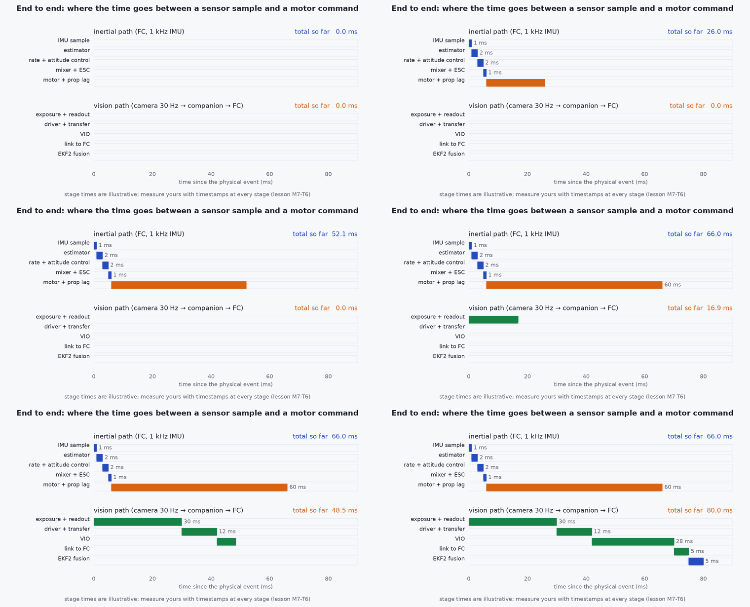
The architecture has five layers: sensors, perception, state estimation, planning and supervision, and flight control with actuators. Data flows forward (sensing to action) and backward (state to planner). Each flow is an interface that two teams or two pieces of software must agree on.
Engineering intuition
Most integration failures are interface failures: a rate assumed to be 30 Hz that is 10 Hz, a pose in ENU consumed as NED, a timestamp of arrival treated as acquisition, a covariance that is a variance. Writing the interfaces as data (not as a diagram only) lets a program find the mismatches before the vehicle does. The same table becomes the Interface Control Document (lesson M7-T17) and the source of integration tests.
Mathematical formulation
Two consistency relations are worth checking for every producer–consumer pair:
For the frame, producer and consumer must declare the same convention, or a conversion node must sit between them (lesson M1-T4): the check is equality of declared frames or the existence of a declared converter.
Architecture and data flow
The table below is the minimum interface list for the reference architecture. Rates are typical and must be replaced by measured values.
| ID | From → to | Content | Rate (typical) | Frame |
|---|---|---|---|---|
| IF1 | IMU → estimator | rate, specific force | 200–1000 Hz | body FRD / FLU |
| IF2 | Camera → VIO | images + stamps | 20–30 Hz | optical |
| IF3 | LiDAR → LIO | point cloud + per-point time | 10–20 Hz | LiDAR |
| IF4 | VIO/LIO → estimator | odometry + covariance | sensor rate | ENU / FLU |
| IF5 | Estimator → PX4 | external odometry | ≥ 30 Hz steady | NED / FRD |
| IF6 | Planner → PX4 | setpoint stream | 10–50 Hz, continuous | NED |
| IF7 | PX4 → planner | vehicle odometry, status | autopilot rate | NED / FRD |
Real-world UAV applications
- Writing the ICD for Capstone 4.
- Reviewing a third-party stack before integration.
- Generating integration tests from the interface list.
- Onboarding new engineers: one table explains the whole system.
Implementation example
This runs as shown: the interface table as data, with a check that every consumer’s rate requirement is met, every frame is declared or converted, and every consumer has a producer.
IF = [  # id, producer, consumer, rate_hz (producer), required_hz (consumer), frame
    ("IF1", "imu", "estimator", 400, 200, "FLU"),
    ("IF2", "camera", "vio", 30, 20, "optical"),
    ("IF3", "lidar", "lio", 10, 10, "lidar"),
    ("IF4", "vio", "estimator", 30, 20, "ENU"),
    ("IF5", "estimator", "px4", 50, 30, "NED"),
    ("IF6", "planner", "px4", 30, 10, "NED"),
]
FRAMES_OF = {"estimator": {"FLU", "ENU", "optical", "lidar"}, "px4": {"NED"}}      # frames each consumer accepts without a converter
CONVERTERS = {("estimator", "px4"): "enu_to_ned bridge"}                               # declared converters

def check(interfaces, accepted, converters):
    problems = []
    for iid, prod, cons, hz, need, frame in interfaces:
        if hz < need: problems.append(f"{iid}: {prod} at {hz} Hz < {cons} needs {need} Hz")
        ok = frame in accepted.get(cons, {frame}) or (prod, cons) in converters
        if not ok: problems.append(f"{iid}: {cons} does not accept frame {frame} and no converter is declared")
    consumers = {c for _, _, c, *_ in interfaces}; producers = {p for _, p, *_ in interfaces}
    problems += [f"{c} consumes data but nothing produces it" for c in consumers if c not in producers and c not in {"px4", "estimator", "vio", "lio"}]
    return problems

assert check(IF, FRAMES_OF, CONVERTERS) == []
bad = IF + [("IF7", "planner", "px4", 5, 10, "ENU")]                                    # too slow and the wrong frame
problems = check(bad, FRAMES_OF, CONVERTERS)
print(problems)
assert len(problems) == 2 and "needs 10 Hz" in problems[0] and "does not accept frame ENU" in problems[1]Common engineering mistakes
A diagram without an interface table
The arrows hide rate, frame and timing assumptions.
No owner per interface
Nobody fixes a mismatch.
Rates quoted from datasheets, not measured
Drivers and load change them.
Forgetting the backward flows
State returning to the planner, health to the supervisor and logs to storage are interfaces too.
Treating the ICD as documentation, not a test source
Generate checks from it.
Failure modes
| Failure mode | How it shows up | Likely cause |
|---|---|---|
| Rate mismatch | Consumer starves or interpolates stale data | Producer slower than the consumer assumes |
| Frame mismatch | Mirrored or rotated motion | Missing conversion |
| Hidden dependency | One failure takes down two functions | Shared power, clock or bus not in the diagram |
| Version drift | Message layout changes break one side | No version in the interface |
Debugging approach
- Measure each interface’s actual rate, latency and frame against the table.
- Run the consistency check in CI on the ICD file.
- Walk each failure mode through the diagram and see where it is detected.
- Use the Architecture Builder’s checker on the design.
Practical exercises
- Add the supervisor flows (health records) to the table with rate and failure behaviour.
- Add a LiDAR-to-estimator path and decide its frame and converter.
- Extend the check to latency budgets and apply it to a 100 ms requirement.
- Build the reference architecture in the Architecture Builder and read every link’s inspector text.
Interview questions
Write an answer in your own words, then reveal the model answer. Nothing is sent anywhere.
Question 1
What makes an architecture diagram useful for integration?
Model answer
An interface table behind it: producer, consumer, rate, frame, units, timestamp semantics and owner for each arrow, checkable by a program.
Question 2
What are the most common interface mismatches?
Model answer
Rate, coordinate frame and timestamp meaning (acquisition versus arrival).
Question 3
Which flows are often forgotten?
Model answer
Backward state flow to the planner, health and covariance to the supervisor, and logging and time distribution.
References and further reading
Primary papers, official documentation and standards. Each claim above that is specific to a tool or version points here.