UAV Systems Engineering · Module 1
M1-T11: UAV communication and onboard architecture
Every arrow in the architecture diagram is a link with a bandwidth, a latency and a way to fail: choose each one on purpose.
A UAV has two communication problems: the radio links to the ground and the buses inside the airframe. Both are bandwidth, latency and reliability budgets, and both fail in ways the autonomy stack must expect.
Learning objectives
After this lesson, you should be able to:
- Distinguish the command and control, telemetry and payload links and their requirements.
- Compute a free-space link budget and the maximum range for a given margin.
- Choose an onboard bus (UART, CAN, Ethernet, USB, SPI, I²) for each device.
- Specify the loss-of-link behaviour for each link.
Conceptual explanation
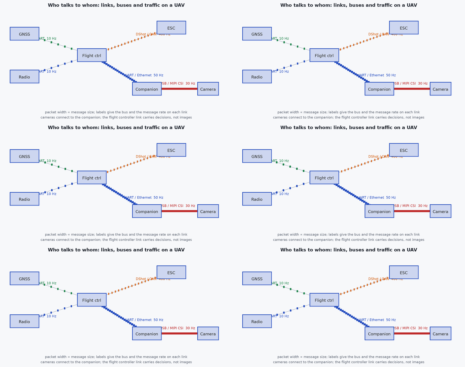
Off-vehicle: a command and control (C2) link (low rate, high reliability, long range), telemetry to a ground station (MAVLink) and a payload link (video, high rate, shorter range). On-vehicle: buses between flight controller, ESCs, sensors and the companion computer.
| Bus | Typical use | Strength | Watch for |
|---|---|---|---|
| UART | GNSS, telemetry radio, companion | simple, common | low rate, no addressing, baud mismatch |
| CAN / DroneCAN | ESCs, GNSS, sensors | robust, multi-drop, differential | bus load, termination, firmware versions |
| SPI / I² | IMU, barometer, magnetometer | short on-board links | I² noise and address clashes, SPI wiring length |
| Ethernet | LiDAR, cameras, companion | high rate, PTP-capable hardware | connectors, weight, switch failure |
| USB | cameras, dongles | convenient | USB 3 noise, connector reliability, power |
Engineering intuition
Match the bus to the requirement: control-critical, low-rate and long cable run suggests CAN; sensor on the same board suggests SPI; high-rate payload suggests Ethernet. Then ask of each link “what does the vehicle do if this goes silent?” and write the answer into the failsafe table (lesson M8-T14). The most dangerous links are the ones with no heartbeat, because silence looks like “nothing to report”.
Mathematical formulation
Free-space path loss and the link budget (established radio engineering):
Doubling distance costs 6 dB; doubling frequency costs 6 dB. The maximum range for a required margin follows by solving for . Real links need extra margin for fading, antenna orientation, obstructions and interference; the free-space result is an upper bound.
- ,
- distance and carrier frequency.
- , ,
- transmit power and antenna gains (dBm, dBi).
- sensitivity
- minimum received power for the data rate (from the radio’s datasheet).
Architecture and data flow
Control path: ground station → C2 radio → flight controller. Autonomy path: companion → FC (UART/Ethernet). Logging path: flight controller → SD card; companion → disk. Time path: GNSS PPS or PTP to sensors. Document every link in the Interface Control Document (lesson M7-T17) with rate, latency, frame, and failure behaviour.
Real-world UAV applications
- Choosing a telemetry radio and antenna for a given range.
- Deciding the bus for a new payload.
- Defining link-loss actions and timeouts.
- Estimating whether live video is feasible at the mission range.
Implementation example
This runs as shown: free-space link budget and the maximum free-space range for a margin, with a check that doubling distance costs 6 dB.
import math

def fspl_db(d_km, f_mhz): return 20 * math.log10(d_km) + 20 * math.log10(f_mhz) + 32.44
def rx_dbm(ptx_dbm, gtx_dbi, grx_dbi, d_km, f_mhz, other_loss_db=0.0): return ptx_dbm + gtx_dbi + grx_dbi - fspl_db(d_km, f_mhz) - other_loss_db
def max_range_km(ptx_dbm, gtx, grx, f_mhz, sensitivity_dbm, margin_db):
    allowed_loss = ptx_dbm + gtx + grx - sensitivity_dbm - margin_db
    return 10 ** ((allowed_loss - 32.44 - 20 * math.log10(f_mhz)) / 20)

assert abs(fspl_db(2, 2400) - fspl_db(1, 2400) - 6.0206) < 1e-3                       # doubling the distance costs 6 dB
assert abs(fspl_db(1, 2400) - 100.04) < 0.05                                          # 1 km at 2.4 GHz is about 100 dB
d = max_range_km(20, 2, 2, 2400, -100, 20)                                            # 100 mW, 2 dBi antennas, -100 dBm sensitivity, 20 dB margin (illustrative)
print(f"free-space upper bound on range: {d:.1f} km (real links need extra margin)")
assert abs(rx_dbm(20, 2, 2, d, 2400) - (-100 + 20)) < 1e-9 and 1 < d < 3Common engineering mistakes
Using the free-space range as the operating range
Obstructions, antenna pattern and interference reduce it a lot; test in the real environment.
No heartbeat on a link
A silent link is indistinguishable from an idle one.
Mixing 2.4 GHz C2, video and Wi-Fi without planning
Self-interference degrades all of them.
Daisy-chaining CAN without termination
Reflections and intermittent faults.
Ignoring latency of video links
A 200 ms video delay is unusable for manual control and must be allowed for in any FPV design.
Failure modes
| Failure mode | How it shows up | Likely cause |
|---|---|---|
| C2 link loss | No operator control | Range, obstruction, interference |
| CAN bus-off | ESCs or sensors disappear | Termination or load fault |
| Link saturation | Rising latency and drops | Too many topics or payload on the telemetry link |
| USB disconnect | Camera stream stops | Connector vibration |
Debugging approach
- Log received signal strength and packet loss against distance and attitude.
- Measure bus load and error counters.
- Test link-loss behaviour by pulling the link in a tethered or simulated test.
- Review the ICD against measured rates.
Practical exercises
- Compute FSPL at 5.8 GHz and 3 km.
- Find the maximum range if the margin requirement is 30 dB.
- Choose buses for ESCs, GNSS, a LiDAR, a stereo camera and a companion computer and justify each.
- Write the loss-of-link action for each link in your architecture.
Interview questions
Write an answer in your own words, then reveal the model answer. Nothing is sent anywhere.
Question 1
How does free-space path loss scale?
Model answer
With 20 log₁₀ of both distance and frequency: 6 dB per doubling of either, so it is an upper bound on range before fading and obstruction.
Question 2
Why prefer CAN for ESCs and some sensors?
Model answer
It is differential, multi-drop and robust to noise over long cables, with built-in error detection.
Question 3
What should every link have?
Model answer
A defined rate and latency budget, a heartbeat or timeout, and a documented failure behaviour.
References and further reading
Primary papers, official documentation and standards. Each claim above that is specific to a tool or version points here.
- PX4: DroneCAN
- MAVLink developer guide
- . . Rappaport, Wireless Communications: Principles and Practice, 2nd ed., Prentice Hall, 2002 (link budgets).
- PX4: peripherals (telemetry radios, GNSS, ESCs)