UAV Systems Engineering · Module 8
M8-T10: Degraded navigation modes
Degraded does not mean broken: define in advance what the vehicle may still do at each level of navigation quality, and what it must stop doing.
A vehicle with a binary healthy or failed view of navigation either flies blind or lands at the first glitch. A ladder of degraded modes keeps it useful while limiting risk, provided the modes, their limits and their transitions are specified and tested.
Learning objectives
After this lesson, you should be able to:
- Define a ladder of navigation modes with entry and exit conditions.
- Derive speed and clearance limits as a function of position uncertainty.
- Design hysteresis so that modes do not chatter.
- Specify the tests that verify each transition.
Conceptual explanation
A degraded mode is a defined, tested operating state with restricted capability. Each mode states: what navigation sources it relies on, what the vehicle may do (speed, altitude, proximity, mission segments), what triggers entry and what permits exit. The modes form a ladder: stepping down is immediate on loss of health; stepping up requires sustained good health.
| Mode | Navigation basis | Allowed | Not allowed |
|---|---|---|---|
| Nominal | GNSS and odometry agree, small | Full mission, full speed | — |
| Degraded (odometry) | Odometry aided, bounded | Reduced speed, increased clearance, return and landing | New legs into unmapped space, close-proximity work |
| Dead reckoning | Inertial only, growing | Hold, or retrace a known path for a limited time | Any manoeuvre needing position accuracy |
| Safe stop | Any | Controlled stop, landing in a safe area | Resuming the mission |
Engineering intuition
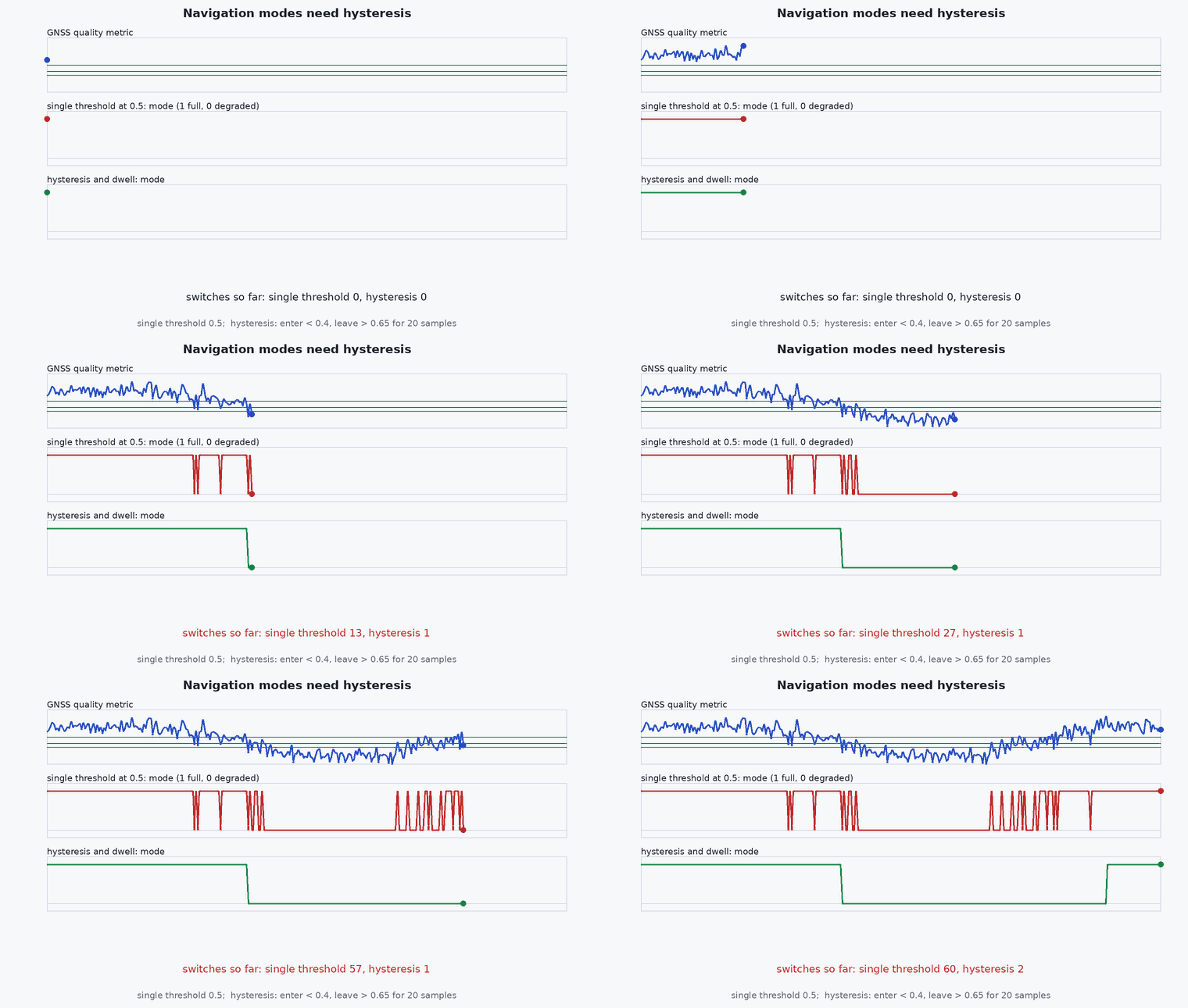
Tie the limits to uncertainty, not to the mode name. The relevant physical question is: with my current position uncertainty , how close can I get to an obstacle and how fast can I fly while still being able to stop within what I know? A mode is then a coarse summary of ranges of and of which sources are healthy, and the limits are a continuous function of inside each mode. Hysteresis comes from asymmetry: it takes one bad sample to lose trust but many good seconds to regain it.
Mathematical formulation
Required clearance grows with uncertainty. With the number of standard deviations to cover (for example 3) and a fixed margin for the vehicle and sensing:
The speed limit follows from stopping distance. With braking deceleration , reaction time (sensing and processing latency, lesson M7-T6) and obstacle detection range :
If no speed is safe: that is the point at which the mode must be at least dead reckoning with a stop. Entry and exit conditions use different thresholds (hysteresis): e.g. enter degraded at , return to nominal only when < σout < for seconds.
Architecture and data flow
Navigation manager (lesson M2-T16) publishes mode, and health. The planner consumes them: it inflates obstacle margins by , limits the trajectory speed to , and refuses mission legs not allowed in the current mode. The mission layer reacts to mode changes (hold, retrace, land). The mode and the limits in force are logged with every setpoint so that investigations can see what the vehicle believed it was allowed to do.
Real-world UAV applications
- GNSS-denied inspection where odometry quality varies with the scene.
- Urban flight crossing GNSS-poor corridors.
- Choosing between continuing, holding and landing when a sensor fails.
- The acceptance criteria and failsafe design of Capstone 4.
Implementation example
This runs as shown: the speed limit as a function of uncertainty (checked against a brute-force stopping-distance search), and a mode selector with hysteresis tested against a chattering uncertainty signal.
import numpy as np

def clearance(sigma, c0=0.5, k=3.0, margin=0.3): return c0 + k * sigma + margin
def v_max(sigma, detect_range=8.0, a_b=3.0, t_r=0.15):
    free = detect_range - clearance(sigma)
    if free <= 0: return 0.0
    return a_b * (-t_r + np.sqrt(t_r**2 + 2 * free / a_b))

def stops_in_time(v, sigma, detect_range=8.0, a_b=3.0, t_r=0.15):
    return v * t_r + v * v / (2 * a_b) <= detect_range - clearance(sigma) + 1e-9

for sigma in (0.1, 0.5, 1.0, 2.0):                                   # the closed form is the largest speed that still stops in time
    v = v_max(sigma); grid = np.linspace(0, 12, 120001)
    best = max(g for g in grid if stops_in_time(g, sigma)) if v > 0 else 0.0
    assert abs(v - best) < 1e-3, (sigma, v, best)
print({s: round(v_max(s), 2) for s in (0.1, 0.5, 1.0, 2.0, 2.5)})
assert v_max(0.1) > v_max(1.0) > v_max(2.0) and v_max(2.5) == 0.0     # more uncertainty, lower speed, eventually none

class ModeSelector:
    """Down immediately when sigma exceeds the entry threshold; back up only after t_hold seconds below the (lower) exit threshold."""
    def __init__(self, s_in=1.0, s_out=0.6, t_hold=5.0):
        self.s_in, self.s_out, self.t_hold = s_in, s_out, t_hold; self.mode = "NOMINAL"; self.good_since = None
    def update(self, t, sigma):
        if sigma > self.s_in: self.mode, self.good_since = "DEGRADED", None
        elif self.mode == "DEGRADED":
            if sigma < self.s_out:
                self.good_since = t if self.good_since is None else self.good_since
                if t - self.good_since >= self.t_hold: self.mode = "NOMINAL"
            else: self.good_since = None
        return self.mode

rng = np.random.default_rng(0); m = ModeSelector(); modes = []
for k in range(300):                                                   # sigma chatters around 0.8: between the two thresholds
    t = k * 0.1; modes.append(m.update(t, 1.2 if k == 50 else 0.8 + 0.05 * rng.standard_normal()))
changes = sum(1 for a, b in zip(modes, modes[1:]) if a != b)
print("mode changes with chattering sigma:", changes)
assert modes[49] == "NOMINAL" and modes[51] == "DEGRADED" and changes == 1 # one drop at the spike, then it stays degraded while sigma hovers between the thresholdsCommon engineering mistakes
Modes defined by names, limits by feeling
Derive the limits from uncertainty, stopping distance and latency, and write them as requirements.
Symmetric thresholds
The mode chatters when the signal hovers at the threshold; use hysteresis and a hold time.
Planner unaware of mode
The mode manager changes but the planner keeps flying the same path: the interface must carry and limits.
No test of the transitions
The ladder is only as good as its least-tested step.
Hard mode switches causing setpoint jumps
Ramp speed and margin changes smoothly.
Failure modes
| Failure mode | How it shows up | Likely cause |
|---|---|---|
| Mode chatter | Rapid toggling and jerky speed | No hysteresis or hold time |
| Silent degradation | Vehicle flies full speed with large uncertainty | Limits tied to mode name, not to |
| Stuck degraded | Never returns to nominal when GNSS is back | Exit condition unreachable or trust never restored |
| Planner collision in degraded mode | Path too close to an obstacle after drift | Clearance not inflated by k |
Debugging approach
- Replay logs with injected sensor loss and check the mode, , speed limit and clearance versus time.
- Check the mode ladder by sweeping up and down across thresholds.
- Verify planner outputs respect with a unit test on recorded trajectories.
- Look for transitions without a logged reason.
Practical exercises
- Compute for , , and .
- Add a mode for “GNSS only” and define its entry and exit conditions.
- Find the hold time that avoids chatter for a signal with 0.1 m noise around the threshold.
- Specify the three tests that verify the step from nominal to degraded in the Failure Simulator.
Interview questions
Write an answer in your own words, then reveal the model answer. Nothing is sent anywhere.
Question 1
What belongs in a degraded-mode definition?
Model answer
The navigation basis, the allowed and forbidden operations, the entry condition, the exit condition with hysteresis, and the verification test.
Question 2
How do you set the speed limit in a degraded mode?
Model answer
From stopping distance: the vehicle must be able to stop, including reaction latency, within the detection range minus the clearance needed for the current position uncertainty.
Question 3
Why use hysteresis between modes?
Model answer
Without it the mode toggles whenever the signal hovers near a threshold; hysteresis plus a hold time makes down-transitions fast and up-transitions deliberate.
References and further reading
Primary papers, official documentation and standards. Each claim above that is specific to a tool or version points here.
- NASA Systems Engineering Handbook (operational concepts and fault management)
- PX4: safety configuration (failsafe actions)
- . . Groves, Principles of GNSS, Inertial, and Multisensor Integrated Navigation Systems, 2nd ed., Artech House, 2013 (integrity).