UAV Systems Engineering · Module 1
M1-T7: Flight controllers, ESCs, motors and propellers
Size the propulsion chain from the requirement backwards: mass, thrust-to-weight margin, then propeller, motor, ESC and battery.
A UAV is only as capable as its weakest actuator link. This lesson names each element of the chain, shows what each contributes, and sizes a propulsion system with simple, checkable arithmetic.
Learning objectives
After this lesson, you should be able to:
- Describe the role of the flight controller, ESC, motor and propeller and the signals between them.
- Size thrust requirements from mass and a thrust-to-weight target.
- Explain motor KV, propeller diameter and pitch, and how they interact with battery voltage.
- List the bench checks to do before the first flight.
Conceptual explanation
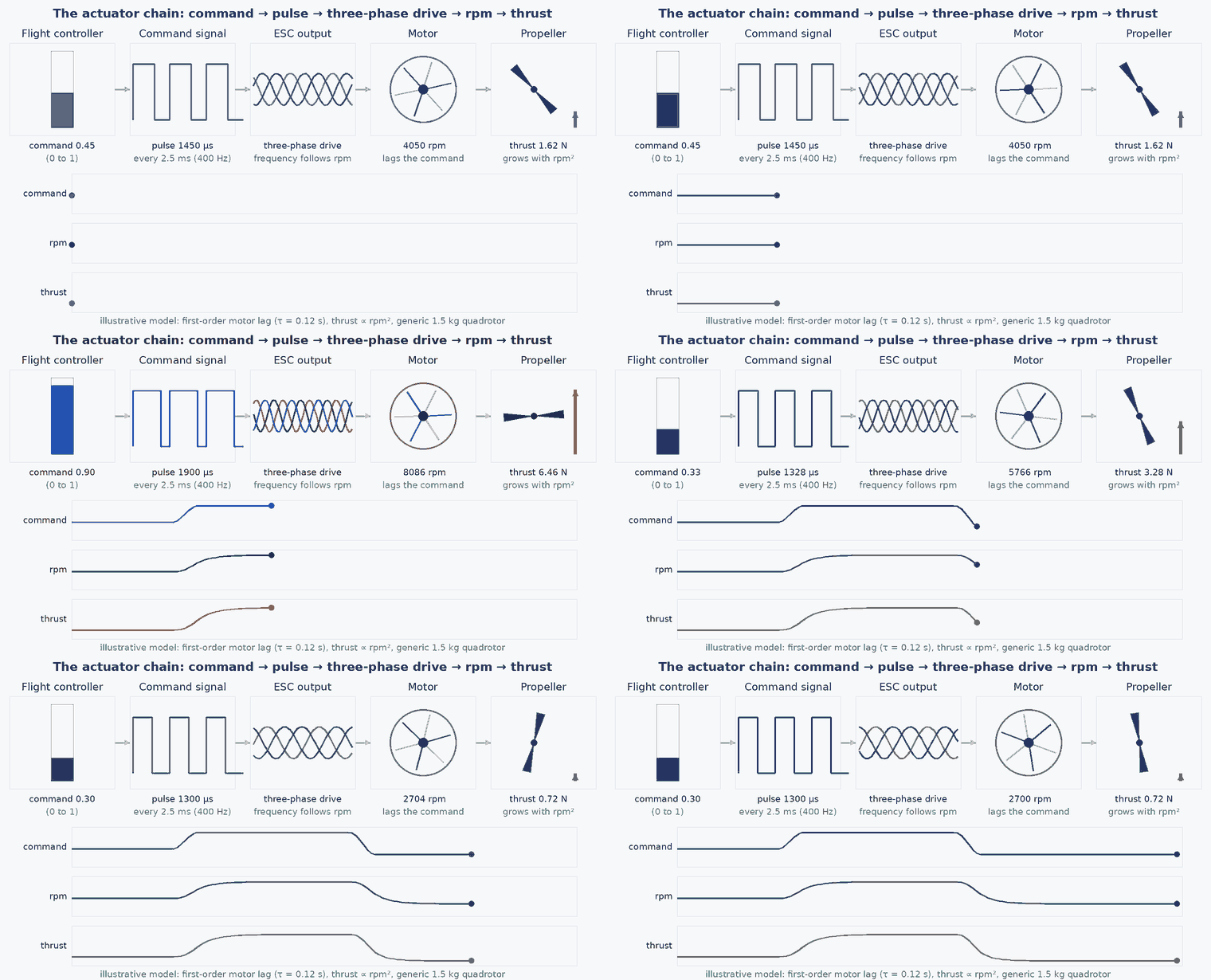
The flight controller (FC) runs estimation and control and produces a normalised command per motor. The electronic speed controller (ESC) converts that command into three-phase drive for a brushless motor, regulating its speed; modern ESCs also report telemetry (rpm, current, temperature). The motor turns electrical power into torque; the propeller turns torque and rotation into thrust. The battery and power distribution close the loop.
Engineering intuition
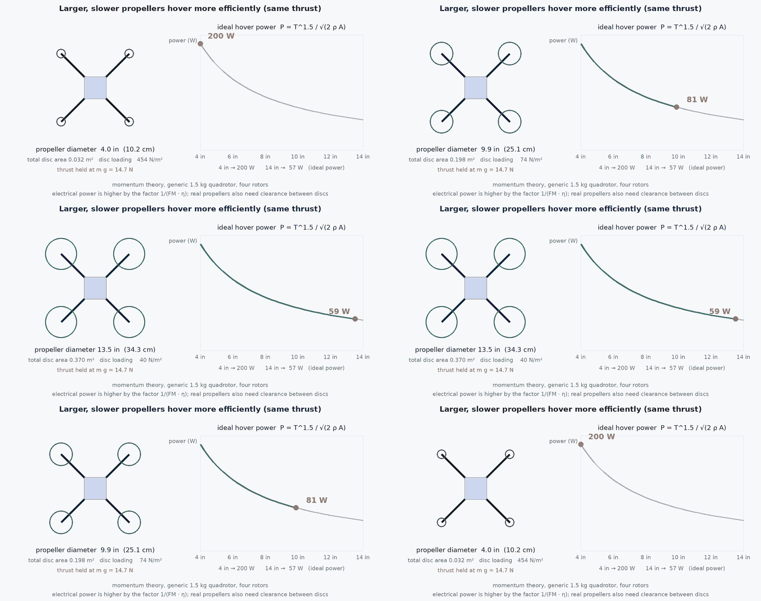
Choose from the requirement backwards. Mass fixes the weight; the margin you want (thrust-to-weight, /) fixes the total thrust; the number of motors fixes thrust per motor; that fixes which propeller and motor combination can produce it efficiently at your battery voltage. A large propeller turning slowly is efficient (low disc loading), a small propeller turning fast is agile but power-hungry. Motor KV (rpm per volt, unloaded) sets how fast the motor tries to spin at a given voltage; a low-KV motor with a large propeller is the usual pairing for endurance, a high-KV motor with a small propeller for agility.
Mathematical formulation
Static requirement and per-motor thrust for motors and mass :
Ideal hover power by momentum theory (the same formula used in the endurance calculator), for total rotor disc area :
- /
- thrust-to-weight ratio of the maximum static thrust to the weight.
- air density, at sea level, ISA.
- FM
- rotor figure of merit (dimensionless, below 1): ideal power over actual aerodynamic power.
- motor and ESC efficiency.
- KV
- motor speed constant (rpm per volt, no load): a datasheet value, not a performance figure under load.
Thrust and power of a real motor-propeller pair at a given voltage come from manufacturer or independent test data (thrust stand), not from formulas. Use formulas to choose candidates and test data to decide.
Architecture and data flow
The FC outputs PWM, DShot or DroneCAN commands to each ESC; the ESC returns rpm, voltage, current and temperature telemetry on the same or a separate bus. This telemetry is valuable for health monitoring and for the mixer: an ESC reporting a stalled motor is a fault that can be handled (module 8).
Real-world UAV applications
- Selecting motors for a 1.5 kg survey platform versus a 5 kg LiDAR platform.
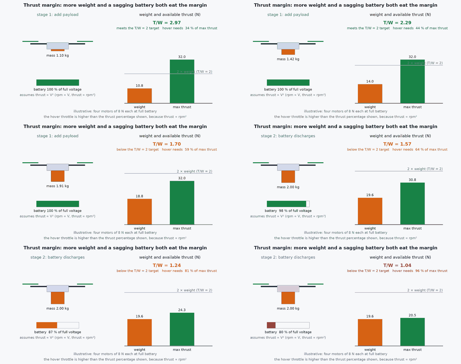
- Evaluating whether an added payload still leaves enough thrust margin at end-of-mission battery voltage.
- Using ESC telemetry for motor-out detection and thermal protection.
- Choosing between 4S and 6S batteries: higher voltage reduces current for the same power.
Implementation example
This runs as shown: it sizes thrust per motor for a mass and / target and flags propeller candidates that cannot reach it. The candidate table is hypothetical: replace it with thrust-stand data for the parts you are considering.
import numpy as np
g, rho = 9.81, 1.225

def required_thrust(mass_kg, motors, tw):
    return tw * mass_kg * g / motors

def hover_power(mass_kg, motors, prop_d_m, fm=0.6, eta=0.8):
    A = motors * np.pi * (prop_d_m / 2) ** 2
    T = mass_kg * g
    return T ** 1.5 / np.sqrt(2 * rho * A) / (fm * eta)

# Hypothetical candidates: (name, prop diameter m, max static thrust per motor N at the planned voltage). Replace with test data.
candidates = [("candidate A", 0.2286, 9.0), ("candidate B", 0.254, 12.5), ("candidate C", 0.3048, 17.0)]
mass, motors, tw = 1.8, 4, 2.0
need = required_thrust(mass, motors, tw)
print(f"need {need:.1f} N per motor for T/W={tw}")
for name, d, tmax in candidates:
    ok = tmax >= need
    print(f"{name}: max {tmax:.1f} N {'OK' if ok else 'too small'}, hover power ~{hover_power(mass, motors, d):.0f} W")
assert abs(need - 8.829) < 1e-3
assert candidates[0][2] >= need and hover_power(mass, motors, 0.3048) < hover_power(mass, motors, 0.2286)Common engineering mistakes
Sizing at full battery voltage
Thrust and available current fall as the pack discharges. Check margin at end-of-mission voltage and with the planned payload.
Choosing KV from the datasheet alone
KV is no-load speed per volt. What matters is thrust and efficiency at the operating point from thrust-stand data.
Undersized ESC current rating
Peak motor current under saturation and transients can exceed the continuous rating: check the ESC’s burst and continuous ratings.
Mixing propeller pitch and direction
A reversed or mismatched propeller gives wrong thrust and torque direction.
Ignoring vibration
Unbalanced propellers inject vibration into the IMU, which degrades attitude and VIO estimates long before anything looks mechanically wrong.
Failure modes
| Failure mode | How it shows up | Likely cause |
|---|---|---|
| Brownout in flight | FC reboots or ESCs reset under a throttle punch | Battery or wiring cannot supply peak current, causing voltage sag below the FC or ESC minimum |
| Motor desync | One motor stutters and stops, vehicle flips | ESC timing or current limit exceeded, bad bearing or damaged winding |
| Overheating | Reduced thrust and early shutdowns on hot days | Disc loading too high, motors at the limit of their rating |
| Thrust deficit at altitude or heat | Cannot hold altitude with payload | Lower air density reduces thrust, / margin was marginal |
Debugging approach
- Log ESC rpm and current; unequal values for a hovering symmetric vehicle point to a motor, propeller or CG problem.
- Weigh the vehicle and measure static thrust on a bench before relying on a calculated /.
- Check vibration with the FC’s vibration metrics before blaming the estimator.
- Use a battery with a known internal resistance and record voltage sag during a step in throttle.
Practical exercises
- A 2.4 kg vehicle with four motors needs . What thrust per motor is required, and what is the hover thrust fraction?
- Use the endurance calculator on the Tools page to compare a 10-inch and a 12-inch propeller at the same mass and battery.
- Why does doubling battery voltage at the same power halve the current, and what does that change in the wiring?
- Estimate how much hover power increases when the payload grows from 0.5 kg to 1.5 kg on a 1.5 kg vehicle.
Interview questions
Write an answer in your own words, then reveal the model answer. Nothing is sent anywhere.
Question 1
Why do large, slow propellers hover more efficiently?
Model answer
For a given thrust, ideal power falls with the square root of the rotor disc area, ; a larger disc accelerates more air by less, wasting less kinetic energy.
Question 2
What does a motor’s KV tell you and what does it not tell you?
Model answer
KV is the unloaded speed per volt. It does not give thrust, current or efficiency under load, which depend on the propeller and battery and must come from test data.
Question 3
What margin of thrust-to-weight do you design for and why?
Model answer
Enough to hold altitude and recover attitude in gusts and at end-of-mission voltage; roughly 2 is a common rule of thumb for general-purpose multirotors, but the requirement should be derived from the mission and verified.
References and further reading
Primary papers, official documentation and standards. Each claim above that is specific to a tool or version points here.