UAV Systems Engineering · Module 1
M1-T8: IMU, barometer, magnetometer and GNSS
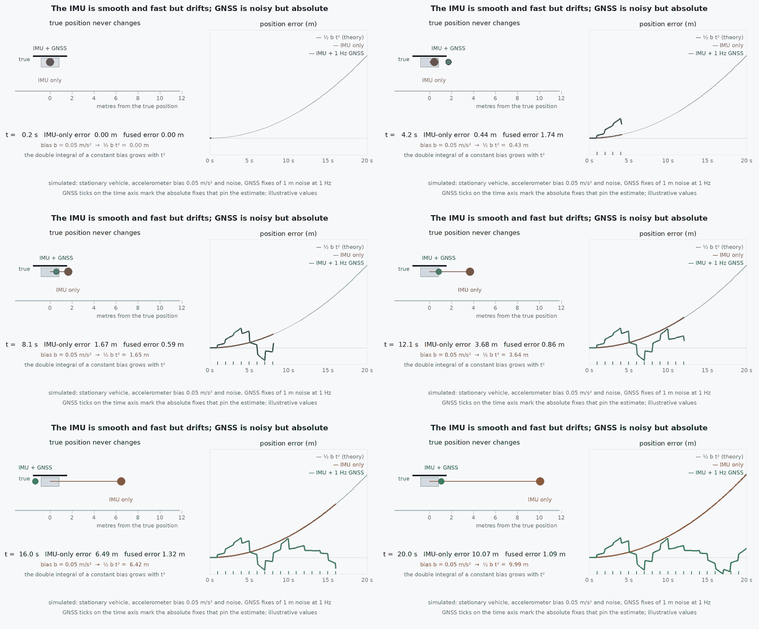
Each sensor sees one thing well and is fooled by another: knowing both halves is the start of sensor fusion.
Every autopilot runs on these four sensors. None is sufficient alone, and each has a characteristic way of lying. This lesson sets out what each measures, its dominant error, and the role it plays in the estimator, so the fusion lessons that follow have something concrete to combine.
Learning objectives
After this lesson, you should be able to:
- State what each of the IMU, barometer, magnetometer and GNSS measures and in which frame.
- Name the dominant error of each and the environment that triggers it.
- Convert pressure to altitude and compute a tilt-compensated heading.
- Explain which state each sensor makes observable and which it does not.
Conceptual explanation
The IMU measures angular rate and specific force at high rate in the body frame. The barometer measures static pressure, which maps to altitude. The magnetometer measures the magnetic field vector in the body frame, which gives heading when the field is known. GNSS measures position and velocity in a global frame.
| Sensor | Measures | Rate (typical) | Dominant error | Fooled by |
|---|---|---|---|---|
| IMU (gyro + accel) | angular rate, specific force | 100–1000 Hz | bias, noise, vibration | vibration, temperature |
| Barometer | static pressure | 10–100 Hz | weather drift, propwash | wind gusts, enclosure pressure, temperature |
| Magnetometer | magnetic field vector | 10–100 Hz | hard- and soft-iron, motor currents | steel structures, power wires, magnets |
| GNSS | position, velocity, time | 1–20 Hz | multipath, atmospheric delay, blockage | urban canyons, jamming, spoofing |
Engineering intuition
Think of two kinds of information. Relative sensors (IMU) are smooth and fast but drift; absolute sensors (GNSS, barometer, magnetometer) are noisy or slow but do not drift. A fusion filter uses the absolute ones to pin down what the relative one cannot hold, and the relative one to fill the gaps between absolute updates. The failure modes are complementary on purpose: an IMU never loses signal, GNSS never drifts.
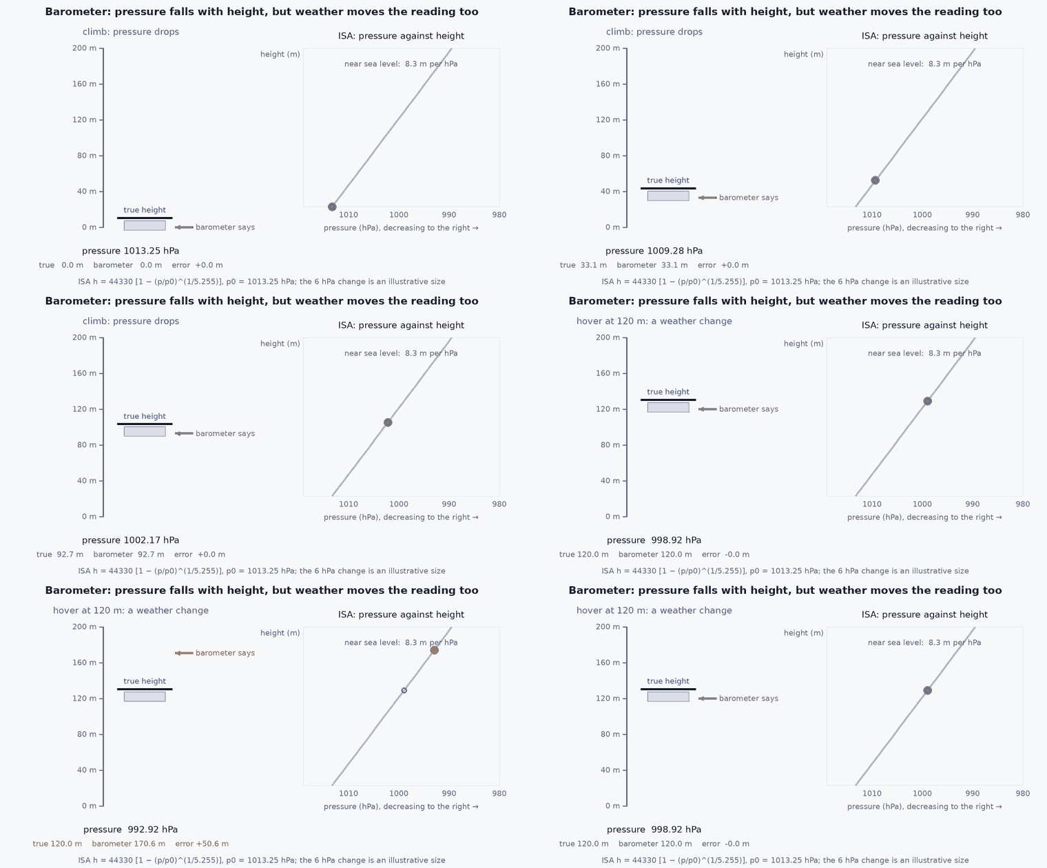
The trap is that each absolute sensor is absolute about something specific: the barometer about pressure altitude (not height above ground), the magnetometer about the local field direction (not true north without declination), GNSS about the antenna position (not the centre of mass). Offsets and reference frames are where integration bugs live.
Mathematical formulation
Pressure to altitude
For the International Standard Atmosphere below 11 km, with sea-level pressure Pa:
A 1 hPa weather change moves the reading by roughly 8 m, so barometric altitude is a relative measurement over a flight, anchored at take-off.
Tilt-compensated heading
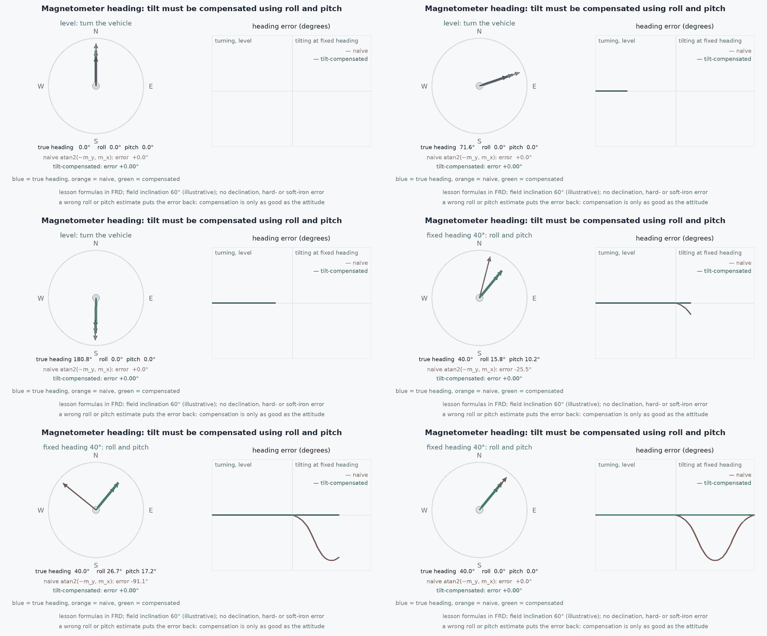
With roll , pitch and body-frame magnetometer in FRD, rotate the field into the horizontal plane then take the angle:
GNSS accuracy
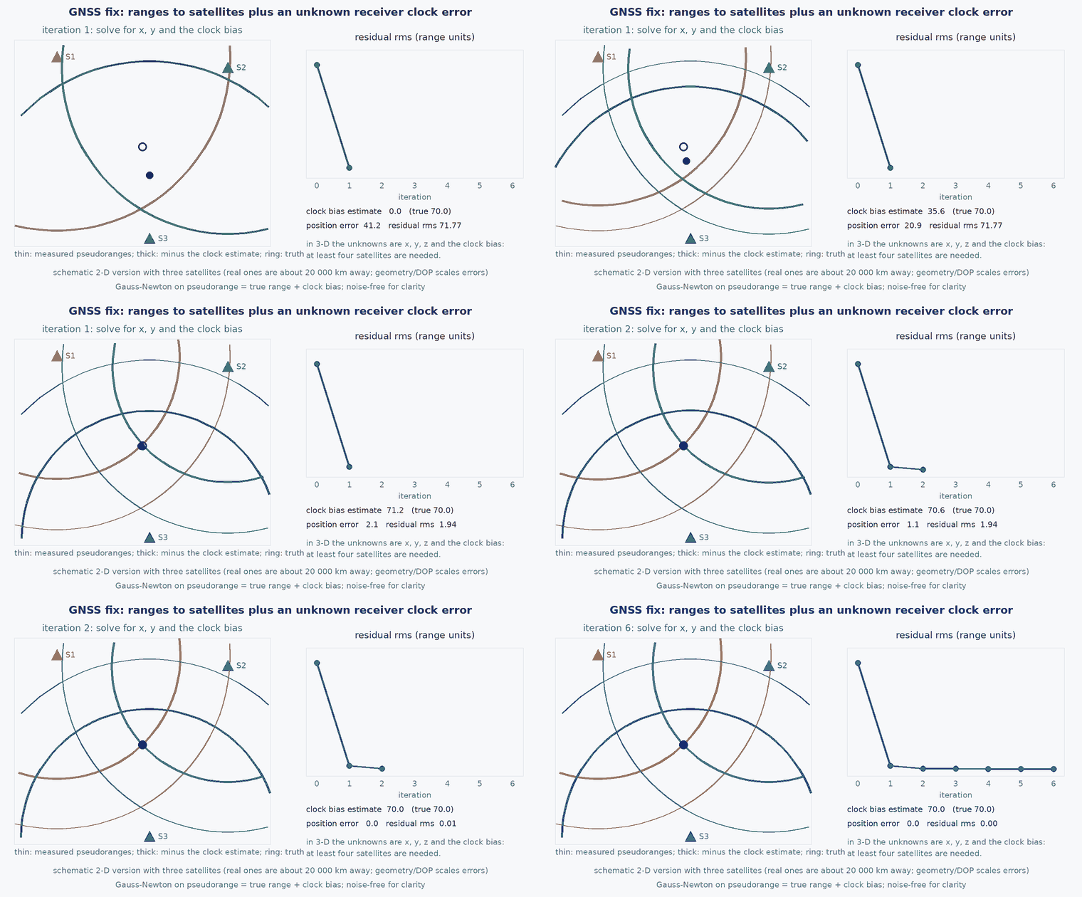
Position error ≈ DOP × range error (lesson M2-T1); velocity from Doppler is typically far more accurate than position differences.
- reference sea-level pressure (Pa); actual local value differs by weather.
- ,
- roll and pitch from the attitude estimate: a heading error appears if they are wrong.
Architecture and data flow
In PX4, drivers publish each sensor to uORB; EKF2 fuses them: IMU for propagation, barometer for height, magnetometer for yaw, GNSS for horizontal position and velocity (and optionally height), with innovation gating on each (lesson M6-T5). When you remove GNSS (lesson M2-T6) or distrust the magnetometer, other sources (vision, LiDAR, external yaw) must supply what they provided.
Real-world UAV applications
- Understanding which EKF2 fusion switches to change for GNSS-denied flight.
- Diagnosing altitude jumps from propwash on the barometer.
- Calibrating the magnetometer away from the airframe wiring.
- Choosing between barometer and rangefinder for height near the ground.
Implementation example
This runs as shown: ISA pressure-to-altitude, its sensitivity, and a tilt-compensated heading checked on a synthetic field (northern-hemisphere style field with inclination).
import numpy as np

def pressure_altitude(p_pa, p0=101325.0): return 44330.0 * (1.0 - (p_pa / p0) ** (1 / 5.255))
assert abs(pressure_altitude(101325.0)) < 1e-9
h = pressure_altitude(89875.0); assert 1000 < h < 1100                     # about 1 km: ISA pressure at 1000 m is 89875 Pa
dh = pressure_altitude(100325.0) - pressure_altitude(101325.0); assert 80 < dh < 90      # 10 hPa lower pressure is about 83 m higher (about 8.3 m per hPa): weather matters

def rot_frd(roll, pitch, yaw):     # body (FRD) -> NED, ZYX
    cr, sr, cp, sp, cy, sy = np.cos(roll), np.sin(roll), np.cos(pitch), np.sin(pitch), np.cos(yaw), np.sin(yaw)
    return np.array([[cy*cp, cy*sp*sr - sy*cr, cy*sp*cr + sy*sr], [sy*cp, sy*sp*sr + cy*cr, sy*sp*cr - cy*sr], [-sp, cp*sr, cp*cr]])

def heading(m, roll, pitch):
    mx, my, mz = m
    mhx = mx * np.cos(pitch) + my * np.sin(pitch) * np.sin(roll) + mz * np.sin(pitch) * np.cos(roll)
    mhy = my * np.cos(roll) - mz * np.sin(roll)
    return np.arctan2(-mhy, mhx)

B_ned = np.array([20.0, 0.0, 45.0])                                        # microtesla: north, east, down (inclination about 66 degrees)
for yaw_deg in (0, 45, 90, 200, -120):
    roll, pitch, yaw = np.radians([12, -8, yaw_deg])
    m_body = rot_frd(roll, pitch, yaw).T @ B_ned                            # the field as the body-fixed sensor sees it
    est = np.degrees(heading(m_body, roll, pitch)); err = (est - yaw_deg + 180) % 360 - 180
    assert abs(err) < 1e-9, (yaw_deg, est)
print("tilt-compensated heading recovers yaw for tilted attitudes")
m_body = rot_frd(*np.radians([12, -8, 45])).T @ B_ned
assert abs(np.degrees(heading(m_body, 0.0, 0.0)) - 45) > 3 # ignoring tilt gives a visible heading errorCommon engineering mistakes
Treating barometric altitude as height above ground
It is relative to a reference pressure that changes with weather; use a rangefinder near the ground.
Calibrating the magnetometer on the bench
The airframe’s iron and currents are part of the field: calibrate on the assembled vehicle, motors off, then check with motors on.
Using GNSS height as precise altitude
Vertical GNSS error is larger than horizontal and the reference is an ellipsoid or geoid.
Ignoring antenna and sensor offsets
Lever arms between GNSS antenna, IMU and centre of mass produce errors in rotation.
Assuming sensors share a clock
Each has latency and a different rate (lesson M7-T8).
Failure modes
| Failure mode | How it shows up | Likely cause |
|---|---|---|
| Altitude steps in hover | Jumps when speed or wind changes | Barometer in a pressure-sensitive location (propwash, airflow) |
| Heading drift with throttle | Yaw changes as motors spin up | Magnetometer near power wires |
| GNSS jump | Position jumps by metres | Multipath or fix change |
| IMU clipping | Attitude diverges in vibration | Vibration at accelerometer saturation |
Debugging approach
- Plot each sensor against the EKF estimate and against another sensor of the same quantity.
- Run the magnetometer-versus-throttle test.
- Inspect IMU spectra and clipping counters.
- Log GNSS accuracy estimates and satellite counts next to position error.
Practical exercises
- Convert 85000 Pa to altitude with the ISA formula and compare with 1 hPa steps.
- Show numerically how a tilt error causes a heading error with an inclination of .
- List which state each of the four sensors makes observable and which remain unobservable without another sensor.
- Estimate how fast barometer-only altitude can drift in a 10 hPa per hour weather change.
Interview questions
Write an answer in your own words, then reveal the model answer. Nothing is sent anywhere.
Question 1
What does each of the four core sensors measure and what is its main failure?
Model answer
IMU: rate and specific force, fails by bias drift and vibration; barometer: pressure/height, fails with weather and propwash; magnetometer: field direction, fails near iron and currents; GNSS: position and velocity, fails by blockage, multipath, jamming and spoofing.
Question 2
Why is barometric altitude a relative measurement?
Model answer
It depends on the local sea-level pressure, which changes with weather by several hectopascals per day, each about 8 m of apparent altitude.
Question 3
Why compensate the magnetometer for tilt?
Model answer
The field has a vertical component; when the vehicle tilts it projects into the horizontal sensor axes and produces a heading error unless roll and pitch are used to level the measurement.
References and further reading
Primary papers, official documentation and standards. Each claim above that is specific to a tool or version points here.
- PX4: Using the EKF2 estimator (sensor fusion options)
- PX4: compass configuration and calibration
- . . Groves, Principles of GNSS, Inertial, and Multisensor Integrated Navigation Systems, 2nd ed., Artech House, 2013, chapters 4 and 6.
- NOAA: magnetic field calculators (declination and inclination)