UAV Systems Engineering · Module 5
M5-T15: Guidance and control integration
Each controller can be correct and the stack can still fail at the interfaces: rates, saturation, hand-overs and mode changes.
A flying system is a stack of loops, each assuming the one below is fast and faithful. Integration is where those assumptions meet reality: a planner that outruns the controller, a saturated actuator that nobody told the outer loop about, a mode switch that makes the setpoint jump. This lesson is about the contracts between layers.
Learning objectives
After this lesson, you should be able to:
- Describe the layers of a guidance, navigation and control stack and typical rates.
- State the contract each layer expects from the one below, including bandwidth separation.
- Explain saturation handling, setpoint continuity and priority between thrust, attitude and yaw.
- Design mode transitions that do not produce setpoint jumps.
Conceptual explanation
Established The layered structure is standard practice. The exact rates, saturation priorities and mode logic differ between autopilots and are implementation-specific.
A multirotor stack is a hierarchy of control loops with decreasing bandwidth upward: rate (fastest), attitude, velocity, position, trajectory, planner, mission. The rule that makes the hierarchy work is bandwidth separation: each loop sees the one below as approximately an identity (its commanded quantity is achieved with small lag), which requires the lower loop to be several times faster than the upper.
The interface between two layers is a contract with four parts: the quantity passed (acceleration, attitude, rate), its frame, its rate and latency, and its limits (what the lower layer can actually deliver). Most integration failures are a violated contract:
- Rate mismatch: a 5 Hz planner feeding a position controller without interpolation produces steps.
- Frame mismatch: ENU commands to an NED controller.
- Silent saturation: the outer loop keeps demanding what the inner loop cannot provide (integrator windup, lost altitude).
- Discontinuity at hand-over: a mode change that switches setpoints without blending produces a transient.
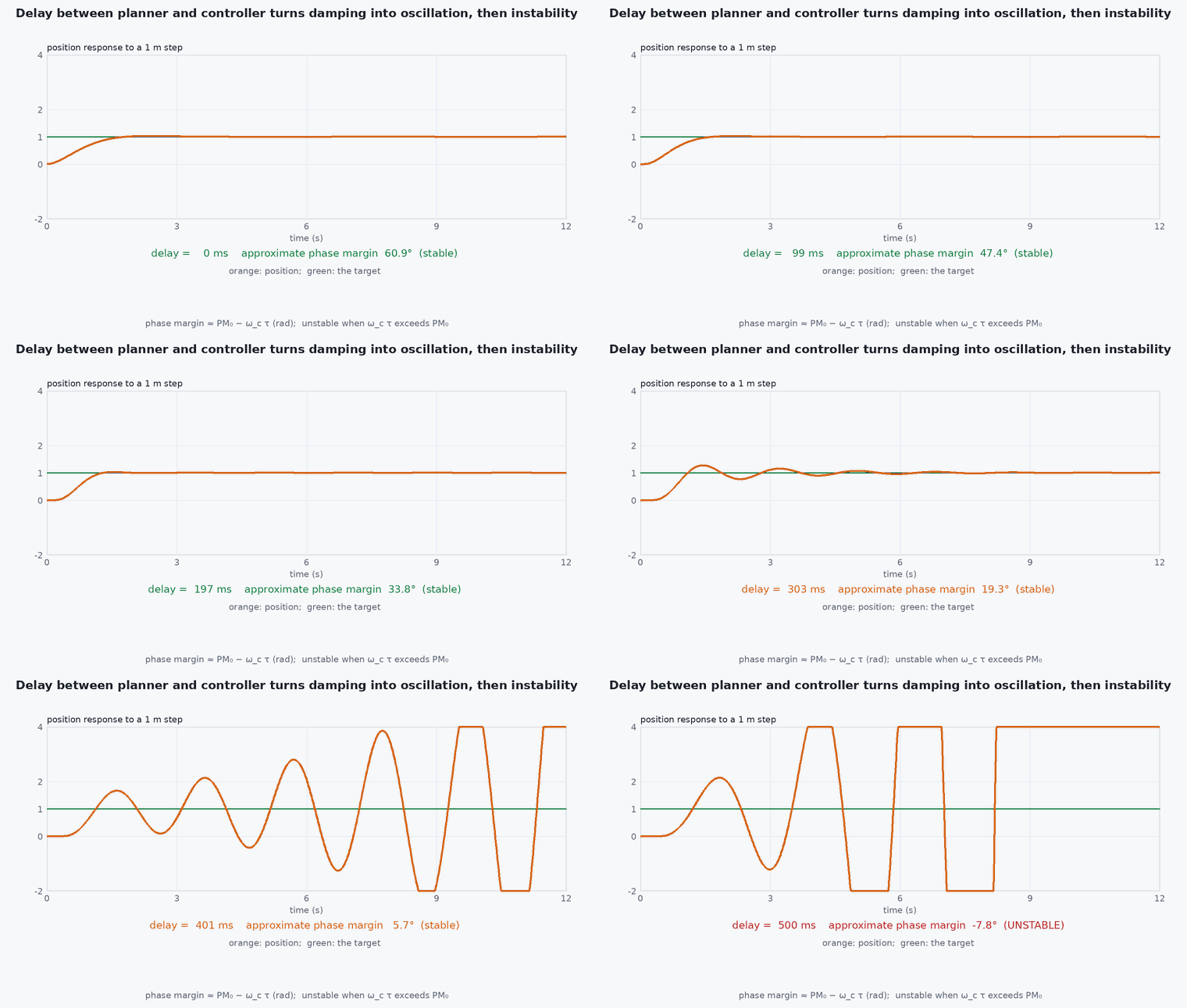
Engineering intuition
Think of a chain of people passing instructions down a line, each faster than the last. If someone mishears, or can’t do what is asked, the chain must tell the upstream person, otherwise the upstream keeps issuing impossible orders. In control terms the lower layer must report saturation upward, and the upper layer must back off (anti-windup, reference limiting).
The second idea is priority under saturation. When the motors cannot provide the commanded thrust and torques together, something has to give. Standard practice is to keep attitude (especially roll and pitch) at the expense of yaw and then of altitude, because losing attitude loses the vehicle while losing a little yaw or height does not. The mixer is where this priority is implemented.
Mathematical formulation
Bandwidth separation can be expressed as a ratio of closed-loop bandwidths. For an outer loop with bandwidth and inner loop , the phase lag of the inner loop at is about for a first-order inner loop:
The phase margin of the outer loop is reduced by this amount, which is why ratios of 3–10 are the working range. Reference limiting for an outer loop whose command passes through a saturated inner loop is a rate limiter: pass through
Mixer priority with desaturation: given thrust and torques , motor commands . If any exceeds its bounds, reduce the yaw torque component first, then the collective thrust, and keep the roll and pitch torques. A simple method scales the yaw term by the largest factor in [0, 1] that keeps all motors in range.
- ,
- outer and inner closed-loop bandwidths (rad/s).
- maximum reference change per step.
- mixer matrix from motor commands to thrust and torques.
Architecture and data flow
Estimator (state, covariance, health) → every layer. Mission manager → goal; planner → path; trajectory generator → , , a, yaw references; position controller → thrust vector and attitude reference; attitude controller → body-rate reference; rate controller → torque and thrust; mixer → motor commands; motors → vehicle. Upward signals: saturation flags, controller-tracking error, estimator health and battery state, so the mission layer can slow down, hold or abort. Every inter-layer message carries a timestamp, so latency between layers can be measured.
Real-world UAV applications
- Integrating a companion-computer planner with an autopilot via offboard setpoints.
- Designing safe mode transitions between manual, position, mission and offboard modes.
- Diagnosing oscillation as a bandwidth-separation violation.
- Defining interface control documents between the planner, controller and estimator teams.
Implementation example
This runs as shown. A two-loop system: an inner first-order loop with bandwidth and an outer loop with bandwidth . The closed loop is ″ + , with damping ratio = ½: overshoot is about 30 % at a ratio of 0.5, 16 % at 1, 4 % at 2 and none from 4 upward. The test sweeps the ratio, confirms the overshoot falls as the inner loop speeds up, and checks the phase-lag formula value.
import numpy as np

def step_overshoot(wi, wo, dt=1e-3, T=20.0):
    y = 0.0; u_in = 0.0; peak = 0.0       # outer P loop gain wo on error; inner first-order loop: u_in -> y with time constant 1/wi
    # y' = wi (u_in - y) ; u_in = wo (r - y)   =>  y'' + wi y' + wi wo y = wi wo r  (second-order system)
    v = 0.0
    for k in range(int(T / dt)):
        u_in = wo * (1.0 - y)
        # integrate as a first-order inner loop on the integrator plant: p' = v, v' = wi (u_in - v)
        v += wi * (u_in - v) * dt; y += v * dt; peak = max(peak, y)
    return peak - 1.0
for ratio in (0.5, 1, 2, 3, 5):
    wo = 2.0; wi = ratio * wo; print(f"inner/outer = {ratio:3.1f}: overshoot {100 * step_overshoot(wi, wo):5.1f} %   phase lag {np.degrees(np.arctan(1 / ratio)):5.1f} deg")
os = [step_overshoot(r * 2.0, 2.0) for r in (0.5, 1, 2, 3, 5)]
assert os[0] > os[1] > os[2] > os[3] - 1e-9 and os[0] > 0.25 and os[1] > 0.1 and os[3] < 0.01        # damping ratio sqrt(wi/wo)/2: overshoot vanishes for wi/wo >= 4 in this model
assert abs(np.degrees(np.arctan(1 / 3)) - 18.4) < 0.1Common engineering mistakes
Tuning the outer loop first
Tune from the inside out: rate, attitude, velocity, position.
Same rate for everything
Running the planner at the controller rate wastes compute; running the controller at the planner rate loses stability.
Silent saturation
The outer loop never learns the actuator limit and winds up.
Step setpoints at mode change
Blend or rate-limit the setpoint at hand-over.
No timestamps between layers
Latency is invisible until it causes a crash.
Failure modes
| Failure mode | How it shows up | Likely cause |
|---|---|---|
| Slow oscillation of position | Large limit cycle around hover | Outer-loop bandwidth too close to inner-loop bandwidth |
| Jump on mode change | Sudden attitude change after the switch | Setpoint discontinuity at hand-over |
| Altitude loss during aggressive moves | Height sag while tilting | Thrust saturation without priority logic |
| Delayed reaction | Vehicle responds late to commands | Accumulated latency between layers |
Debugging approach
- Plot commanded against measured value for every loop to see which one lags.
- Check the ratio of loop bandwidths from step-response rise times.
- Log the saturation flags and mixer output.
- Trace one setpoint through all layers with timestamps to find the delay.
Practical exercises
- Measure the rise time of each loop of a simulated vehicle and compute the bandwidth ratios.
- Add actuator saturation to the example and implement rate-limited references.
- Write the interface contract (quantity, frame, rate, latency, limits) for the planner → controller boundary.
- Design a mode transition from hover to offboard that avoids a setpoint jump.
Interview questions
Write an answer in your own words, then reveal the model answer. Nothing is sent anywhere.
Question 1
What is bandwidth separation and why do you need it?
Model answer
Each loop must be several times slower than the one beneath it so that the lower loop acts as an almost ideal actuator. Otherwise its phase lag eats the outer loop’s phase margin and causes oscillation.
Question 2
How should a mixer prioritise under saturation?
Model answer
Preserve roll and pitch authority first, then collective thrust, and give up yaw first, because losing attitude loses the vehicle.
Question 3
What goes into an interface contract between two layers?
Model answer
The quantity and frame, the rate and latency, and the limits the lower layer can deliver, plus how saturation is reported upward.
References and further reading
Primary papers, official documentation and standards. Each claim above that is specific to a tool or version points here.