UAV Systems Engineering · Module 5
M5-T14: Trajectory tracking
A trajectory is only as good as the controller that follows it. Feedforward and the thrust-vector construction turn a reference into attitude commands.
Planners hand over a time-parameterised reference; the tracking controller is what makes the vehicle follow it. A pure feedback controller always lags a moving reference. Adding the reference acceleration as feedforward removes most of that lag, and the thrust-vector construction connects the outer position loop to the attitude loop.
Learning objectives
After this lesson, you should be able to:
- Write the position tracking law with feedback and acceleration feedforward and the closed-loop error dynamics.
- Construct the desired thrust vector and the desired attitude from it, including the yaw reference.
- Compute standard tracking error metrics.
- Explain why the tracking error depends on the reference’s derivatives and the inner-loop bandwidth.
Conceptual explanation
Established The thrust-vector construction follows the geometric tracking control literature (Lee, Leok and McClamroch 2010) and common autopilot practice. Specific autopilots implement variants with different saturation and priority rules.
Given a reference with derivatives and , define the errors and . A PD law with acceleration feedforward commands
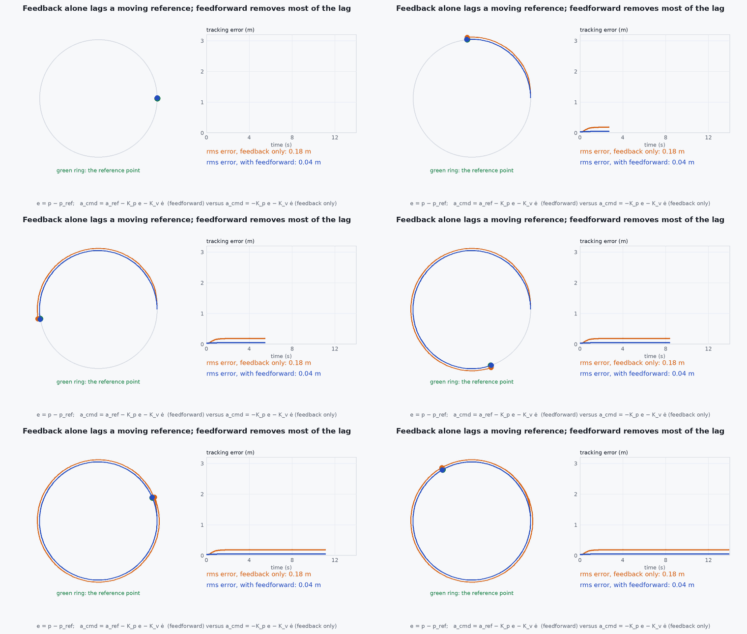
With the inner loops fast enough to treat the commanded acceleration as achieved, the error obeys , a linear, exponentially stable system with no dependence on the trajectory. Without the feedforward term the error obeys the same equation driven by −, so the tracking error is proportional to the reference acceleration.
Engineering intuition
Chasing a car by only looking at the gap always leaves you behind: you accelerate when the gap has already opened. Knowing the car’s planned acceleration lets you accelerate at the same moment. That is feedforward. With it the feedback only has to correct disturbances and model errors, so the gains can be modest and the response smooth.
The outer loop cannot be faster than the inner. If the attitude loop takes 0.15 s to realise a commanded tilt, the position loop assumes a wrong acceleration for that long. Tracking aggressive references demands bandwidth in the inner loops, or a reference whose derivatives stay within what they deliver.
Mathematical formulation
For a multirotor with mass , total thrust along the body axis and the world frame with up, . The desired thrust vector from the commanded acceleration is
Given a desired yaw , the other axes follow from a heading vector :
The construction is singular when is parallel to , which is only the case when the desired thrust is horizontal (more than of tilt, outside any normal envelope). Practical autopilots limit the tilt and prioritise the thrust direction over yaw when the limit is reached. Common metrics for evaluating tracking are the RMS and maximum position error:
- ,
- position and velocity gains .
- ,des
- desired body axis (thrust direction).
- reference yaw angle.
Architecture and data flow
Trajectory generator (or planner) → sample , , , at the controller’s rate → position controller (feedback plus feedforward) → thrust magnitude and desired attitude → attitude controller → rate controller → motor mixer. The estimator supplies and ; its latency and noise enter the error directly, so tracking performance cannot be better than estimation quality allows. In PX4 offboard mode the trajectory setpoint message carries position, velocity and acceleration fields, so feedforward terms can be supplied (check the documentation of your version for how they are combined).
Real-world UAV applications
- Following minimum-snap trajectories in aggressive flight.
- Inspection paths with a required position accuracy.
- Formation and coordinated flight following reference time laws.
- Testing controllers by comparing error metrics on standard figure-eight references.
Implementation example
This runs as shown. A point-mass model with a first-order lag (0.1 s) between commanded and achieved acceleration tracks a circle of radius 5 m at 3 m/s. The test shows that feedforward of the reference acceleration reduces the RMS error, and checks the thrust-vector construction gives an orthonormal with the right thrust direction.
import numpy as np

def ref(t, r=5.0, w=0.6):
    return (np.array([r * np.cos(w * t), r * np.sin(w * t)]), np.array([-r * w * np.sin(w * t), r * w * np.cos(w * t)]),
            np.array([-r * w * w * np.cos(w * t), -r * w * w * np.sin(w * t)]))
def run(ff, Kp=9.0, Kv=6.0, tau=0.1, dt=0.005, T=20.0):
    p, v, a = np.array([5.0, 0.0]), np.array([0.0, 3.0]), np.array([-1.8, 0.0]); errs = []
    for k in range(int(T / dt)):
        pr, vr, ar = ref(k * dt)
        a_cmd = (ar if ff else 0.0) - Kp * (p - pr) - Kv * (v - vr)
        a += (a_cmd - a) / tau * dt; v = v + a * dt; p = p + v * dt            # first-order lag between commanded and achieved acceleration
        if k * dt > 5: errs.append(np.linalg.norm(p - pr))
    return np.sqrt(np.mean(np.square(errs))), max(errs)
(r0, m0), (r1, m1) = run(False), run(True)
print(f"RMS error without feedforward {r0:.3f} m, with feedforward {r1:.3f} m (max {m1:.3f} m)")
assert r1 < 0.5 * r0
def desired_attitude(a_cmd, yaw, m=1.5, g=9.81):
    F = m * (a_cmd + np.array([0, 0, g])); b3 = F / np.linalg.norm(F)
    c = np.array([np.cos(yaw), np.sin(yaw), 0.0]); b2 = np.cross(b3, c); b2 /= np.linalg.norm(b2); b1 = np.cross(b2, b3)
    return np.column_stack([b1, b2, b3]), np.linalg.norm(F)
R, T = desired_attitude(np.array([2.0, -1.0, 0.5]), 0.7)
print(f"thrust {T:.2f} N, orthonormal: {np.allclose(R.T @ R, np.eye(3), atol=1e-12)}, det {np.linalg.det(R):.3f}")
assert np.allclose(R.T @ R, np.eye(3), atol=1e-12) and abs(np.linalg.det(R) - 1) < 1e-12 and np.allclose(R[:, 2] * T, 1.5 * np.array([2.0, -1.0, 10.31]))Common engineering mistakes
No feedforward on curved references
Constant lag proportional to the reference acceleration.
Time-base mismatch
The reference is sampled with a different clock than the estimate; the error contains a time offset times the velocity.
Aggressive reference beyond inner-loop bandwidth
Position error grows and the vehicle cuts corners.
Yaw reference with a discontinuity
wrap commands a full turn; wrap the yaw error to ±.
Ignoring tilt and thrust limits
The commanded acceleration cannot be produced; saturate and prioritise explicitly.
Failure modes
| Failure mode | How it shows up | Likely cause |
|---|---|---|
| Steady lag behind the reference | Constant offset along the path | Missing feedforward, or latency in the reference or estimate |
| Oscillation in tracking | Growing wobble at high speed | Outer-loop gain too high relative to inner-loop bandwidth |
| Altitude sag in turns | Loss of height in banked turns | Thrust magnitude not compensated for tilt; thrust saturation |
| Yaw spins at the wrap | Sudden full rotation | Unwrapped yaw error |
Debugging approach
- Plot position error against time and against reference acceleration: correlation indicates missing feedforward.
- Check the clocks: shift the reference by and see whether the error decreases.
- Plot commanded against achieved tilt to measure inner-loop lag.
- Check thrust and tilt saturation flags in the log.
Practical exercises
- Sweep the circular reference angular rate from 0.3 to 1.2 rad/s and plot the RMS error with and without feedforward.
- Add a 50 ms estimation delay and show the effect on the RMS error.
- Increase the lag to 0.3 s and tune the gains to restore stability.
- Implement tilt saturation at and report the change in tracking error at 1.2 rad/s.
Interview questions
Write an answer in your own words, then reveal the model answer. Nothing is sent anywhere.
Question 1
Why add acceleration feedforward?
Model answer
Feedback acts only after an error has appeared, so a pure PD controller lags a moving reference by an amount proportional to its acceleration. Feedforward supplies the acceleration needed at the moment it is needed.
Question 2
How is the desired attitude computed from the desired acceleration?
Model answer
The desired thrust vector gives the body axis and the thrust magnitude; a yaw reference fixes the remaining rotation about that axis through cross products.
Question 3
What limits how aggressive a reference can be tracked?
Model answer
Actuator and tilt limits, inner-loop bandwidth and estimation quality: the achieved acceleration must follow the commanded one.
References and further reading
Primary papers, official documentation and standards. Each claim above that is specific to a tool or version points here.