UAV Systems Engineering · Module 6
M6-T15: Hardware-in-the-Loop simulation
HIL puts the real controller in the loop. It finds timing, load and integration problems that SITL cannot, and still cannot find sensor or vibration problems.
Between SITL and flight there is a middle step: run the real firmware on the real flight controller, connected to a simulator that stands in for the world. HIL finds problems of the target (CPU load, timing, driver configuration, serial links, power) and of the integration (wiring, baud rates, companion connection) without risking a vehicle.
Learning objectives
After this lesson, you should be able to:
- Explain what HIL verifies that SITL does not, and what it still cannot.
- Describe the HIL data flow and the simulated sensor interface.
- Plan a HIL test matrix for an integrated system.
- Identify when HIL is worth the effort and when bench or flight tests are better.
Conceptual explanation
Implementation-specific PX4 supports HIL through a MAVLink-based HIL interface with a simulator, in a dedicated HIL configuration of the firmware. The exact procedure and simulator support change between releases, and HIL for some vehicle types is less maintained than SITL: check the current documentation before planning around it.
In hardware-in-the-loop simulation the real flight controller runs the real firmware. Its sensor drivers are replaced by a HIL interface: a host computer runs the simulator and sends simulated sensor messages (IMU, GNSS, barometer, magnetometer) to the controller over a serial or USB link, and receives actuator outputs, closing the loop. Motors are disconnected (propellers off) or replaced by dummies.
Compared with SITL, HIL exercises:
- Target timing and load: the real CPU, RTOS, scheduling and memory; if the stack overruns its cycle on the real processor, HIL shows it.
- Configuration and wiring: the real serial ports, baud rates, power, GPIO and connector pinouts used with the companion and peripherals.
- Boot, parameters, storage and logging on the real target.
- End-to-end integration with a real companion computer, real links and the real ground station.
Engineering intuition
HIL tests the vehicle’s brain on the bench, with a simulated body and world. It is the first place a CPU overload, a misconfigured UART or a boot-order bug will show. But the sensors are still imaginary: HIL will not find a vibration-corrupted accelerometer, a noisy magnetometer next to a power wire, a camera whose exposure fails in sun, or a motor that behaves differently from its model.
Think of the progression as widening the truth: SITL proves the logic, HIL proves the target and integration, bench tests prove the sensors and actuators, tethered and free flights prove the dynamics and the environment. Each layer catches defects the previous cannot.
Mathematical formulation
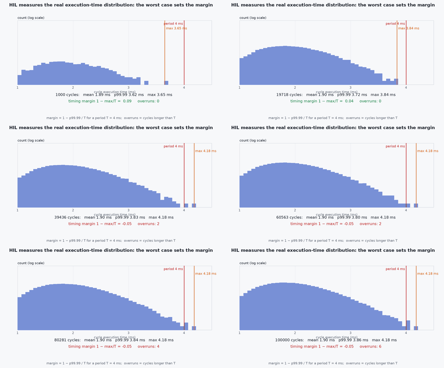
Two timing measurements make HIL quantitative. The control-loop margin: with a loop period and measured worst-case execution time the utilisation margin is
and the simulator-to-controller latency introduced by the link and the host: it adds directly to the loop delay and should be measured and kept below what the controllers tolerate (a small fraction of the shortest control time constant), or the HIL results are pessimistic or optimistic in ways that are hard to separate from the system’s own behaviour. Because the HIL link is serial, its bandwidth bounds the sensor rates: a stream of bytes per message at Hz needs 10 bit/s on an 8N1 serial link.
- worst-case execution time of one cycle.
- cycle period.
- added latency from the HIL link and host.
Architecture and data flow
Simulator on the host → HIL sensor messages (MAVLink HIL_SENSOR, HIL_GPS and related) over USB or serial → flight controller firmware in HIL mode → HIL actuator controls (MAVLink) → simulator; MAVLink and DDS to QGC and the companion as normal. A real companion computer can run the full autonomy stack with simulated camera or lidar data supplied from the simulator over Ethernet, so the companion’s load and latency are tested too.
Real-world UAV applications
- Verifying the firmware build and parameter set on the real target before a first flight.
- Load and timing tests with the full companion and communication stack.
- Failsafe and mode-logic tests on the real flight controller.
- Regression tests before each flight campaign.
Implementation example
This runs as shown. A margin calculator for a real-time loop from measured execution times (here synthetic samples standing in for HIL measurements), with the serial bandwidth check for the sensor stream.
import numpy as np
rng = np.random.default_rng(4)
T = 1 / 250.0                                                        # a 250 Hz control cycle
exec_us = rng.gamma(shape=20, scale=95.0, size=100000)               # synthetic execution times in microseconds (mean about 1.9 ms)
exec_us[rng.random(exec_us.size) < 1e-4] += 900.0                    # rare long cycles (cache misses, logging)
cmax = np.percentile(exec_us, 99.99) * 1e-6
print(f"p99.99 execution time {cmax * 1e3:.2f} ms of {T * 1e3:.1f} ms period -> margin {1 - cmax / T:.2f}, overruns: {(exec_us * 1e-6 > T).sum()}")
assert 1 - cmax / T > 0.0
def serial_bits_per_s(msg_bytes, rate_hz, overhead=12): return 10 * (msg_bytes + overhead) * rate_hz         # 8N1: 10 bits per byte, frame overhead per message
bw = serial_bits_per_s(44, 250) + serial_bits_per_s(36, 10)          # an IMU-sized message at 250 Hz and a GNSS-sized one at 10 Hz (illustrative sizes)
print(f"HIL stream needs about {bw / 1000:.0f} kbit/s; a 921600 baud link has {921600 / 1000:.0f} kbit/s")
assert bw < 921600Common engineering mistakes
Flying propellers on during HIL
Props off, always: actuators receive real commands.
Reading HIL success as sensor validation
Sensors are simulated; real sensors need bench and flight tests.
Ignoring link latency
The HIL link adds delay that distorts control behaviour; measure it.
Not matching the HIL build to the flight build
Test the exact binary and parameters to be flown, apart from the HIL switch.
No timing measurement
Without execution-time data, a pass hides a margin of nearly zero.
Failure modes
| Failure mode | How it shows up | Likely cause |
|---|---|---|
| No sensor data on the controller | Estimator not starting | HIL link, baud rate or configuration mismatch |
| Control loop overruns | Late cycles, scheduler warnings | CPU overloaded by logging, extra modules or heavy comms |
| Unrepresentative results | Behaviour differs from flight | Latency or sensor models not representative |
| Hardware damage on the bench | Unexpected motor spin | Props on or outputs not disabled |
Debugging approach
- Check the console for scheduler overrun warnings and CPU load.
- Measure HIL latency with timestamps on both ends.
- Compare HIL and SITL logs for the same scenario to separate target from model effects.
- Verify the firmware and parameter hashes are those intended for flight.
Practical exercises
- Write a HIL test matrix with ten tests (mode changes, link loss, sensor loss, companion loss) and their pass criteria.
- Compute the serial bandwidth for the HIL stream of your vehicle at your rates.
- Measure and plot the loop execution time on your target.
- List five defects HIL can find and five it cannot.
Interview questions
Write an answer in your own words, then reveal the model answer. Nothing is sent anywhere.
Question 1
What does HIL verify that SITL does not?
Model answer
The real target: CPU load and timing, drivers, serial links, boot and storage, wiring and the integration with a real companion, using the real firmware binary.
Question 2
What can HIL not verify?
Model answer
Real sensor performance, vibration, magnetic interference, motors and aerodynamics, power and thermal behaviour: these need bench and flight tests.
Question 3
How would you decide whether HIL is worth it?
Model answer
When the risk is in the target or the integration (tight timing, many interfaces, new hardware) and a bench test with real sensors cannot cover it; for pure logic, SITL is cheaper.
References and further reading
Primary papers, official documentation and standards. Each claim above that is specific to a tool or version points here.