UAV Systems Engineering · Module 6
M6-T16: Companion computer integration
The companion computer is a powerful, fragile guest on a safety-critical vehicle. Integrate it so that its failure is a managed event.
A companion computer brings perception and planning to the vehicle, and brings new ways to fail: brown-outs, thermal throttling, crashed processes, filled disks, noisy buses. A good integration assumes it will fail and defines what the vehicle does when it does.
Learning objectives
After this lesson, you should be able to:
- Specify power and grounding for a companion computer on a UAV and avoid brown-out coupling.
- Choose and configure the data link (UART, Ethernet) between companion and autopilot.
- Design a heartbeat and watchdog scheme with defined actions.
- List the checks to make during bench integration before first flight.
Conceptual explanation
Implementation-specific The recommendations are general engineering practice for companion computers on PX4/ArduPilot vehicles. Specific wiring, port names and parameters depend on the flight controller and the companion board: use their hardware documentation.
Five integration areas, in the order they usually cause trouble:
- Power: the companion draws variable, sometimes large, current and generates noise. Give it its own regulated supply (not the flight controller’s 5 rail), size for the peak, and protect the avionics from its transients. A brown-out of the companion in flight must not reset the flight controller.
- Link: a UART with hardware flow control or Ethernet/USB networks; match baud rates, voltage levels (3.3 logic), and cable quality; keep cables short and shielded away from motors.
- Time: the companion and the flight controller have different clocks; agree on how timestamps are related (see the synchronisation lessons) before fusing any data.
- Supervision: processes crash, and disks fill. Run autonomy software under a supervisor (systemd or equivalent) with restart limits, log rotation and health reporting.
- Failure behaviour: a defined, tested autopilot action when the companion goes silent: for example hold, return or land. For offboard control, the stream-loss failsafe is exactly this.
Engineering intuition
The autopilot is the pilot-in-command: it must stay alive and in control whatever the companion does. Design the interface so that all authority flows from the companion to the autopilot as requests that the autopilot checks and can ignore, and so that silence from the companion is itself a signal. In the other direction, the companion should treat the autopilot link as unreliable and monitor it: if the companion stops receiving the vehicle state, it should stop commanding.
The most common real-world faults are mundane: a power supply that sags when the GPU starts, a connector that vibrates loose, a thermal throttle that makes a 20 Hz node run at 8 Hz, a USB device that resets the bus. Test those, not just the software.
Mathematical formulation
Power budget with margin: for peak current at supply voltage , with regulator efficiency and a derating factor (for example 1.5 for transients):
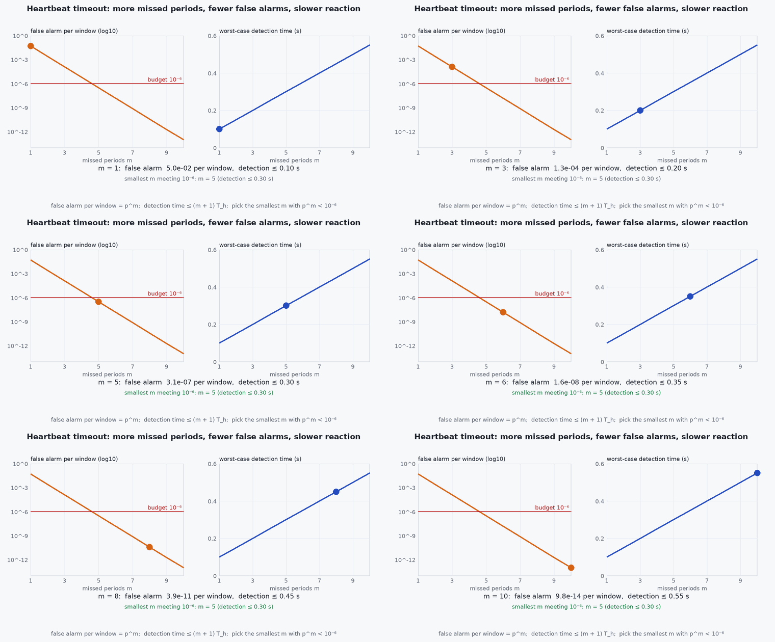
Heartbeat supervision: with a heartbeat period , a loss timeout ( missed beats) and a decision and action time , the worst-case time from companion failure to vehicle response is . The false-alarm probability with independent beat loss probability per message is per window, so with % and it is per window; the detection delay grows with , giving the usual trade-off between detection speed and false alarms. Clock offset: with a one-way link delay estimate from round-trip measurements, the offset estimate error is at most half the round-trip asymmetry.
- ,
- heartbeat period and loss timeout.
- number of consecutive missed beats before declaring loss.
- ,
- regulator efficiency and derating factor.
Architecture and data flow
Battery → power distribution → (a) flight controller with its own power module, (b) companion through a dedicated regulator with input filtering. Companion ↔ flight controller: UART (TELEM port) or Ethernet carrying MAVLink and/or uXRCE-DDS, with heartbeats both ways. Sensors for perception connect to the companion (USB, MIPI CSI, Ethernet), and their timestamps are related to the flight controller clock by hardware trigger or software synchronisation. A supervisor on the companion restarts processes and reports health; the flight controller’s failsafe parameters define the response to loss.
Real-world UAV applications
- Fitting a Jetson or similar board to a PX4 vehicle with ROS 2.
- Defining the bench acceptance tests for a new companion integration.
- Designing the loss-of-companion behaviour for a vision-aided mission.
- Writing the power and interface sections of the interface control document.
Implementation example
This runs as shown. A heartbeat monitor with the parameters from the maths section, checked against a simulated link with random loss and one real outage: it reports detection delay and false alarms, and the supervisor logic that decides the action.
import numpy as np
rng = np.random.default_rng(9)
def monitor(arrivals, Th=0.1, m=3, T_end=600.0):
    """arrivals: sorted heartbeat arrival times. Returns the list of times at which the loss of link is declared."""
    declared = []; last = 0.0; down = False
    for t in np.arange(0.0, T_end, Th / 2):
        got = arrivals[(arrivals > last) & (arrivals <= t)]
        if got.size: last = got[-1]; down = False
        if not down and t - last > m * Th: declared.append(t); down = True
    return declared
Th, p_loss = 0.1, 0.01
beats = np.arange(0.0, 600.0, Th); keep = rng.random(beats.size) > p_loss
outage = (beats > 300.0) & (beats < 305.0); keep &= ~outage                          # one real 5 s outage starting at t = 300 s
arr = beats[keep] + 0.002
events = monitor(arr, Th, m=3, T_end=600.0)
real = [e for e in events if 300.0 <= e <= 305.0]; false = [e for e in events if not (300.0 <= e <= 305.0)]
print(f"declared losses: {len(events)}; detection delay of the real outage {real[0] - 300.0:.2f} s; false alarms {len(false)}")
assert len(real) == 1 and 0.3 <= real[0] - 300.0 <= 0.5 and len(false) <= 2
print("expected false alarms for m = 3: about", round(600 / Th * p_loss ** 3, 4), "per run (independent loss)")Supervising an autonomy process with systemd (a reference unit; adapt the paths and the user):
[Unit]
Description=UAV autonomy stack
After=network.target

[Service]
User=uav
ExecStart=/opt/uav/launch.sh
Restart=on-failure
RestartSec=2
StartLimitIntervalSec=60
StartLimitBurst=5
WatchdogSec=5

[Install]
WantedBy=multi-user.targetCommon engineering mistakes
Powering the companion from the flight controller’s 5 V rail
Current spikes brown out the autopilot; use a dedicated regulator.
No defined action for companion failure
The vehicle’s behaviour then depends on whatever the last setpoint was.
Restarting forever
A crash loop can mask a persistent fault and flood logs; use restart limits and escalate to a safe state.
Ignoring thermal throttling
Frequency drops make the stack slower precisely when it is busiest; monitor temperature.
Unverified cable and connector quality
Vibration loosens connectors; secure and strain-relieve them.
Failure modes
| Failure mode | How it shows up | Likely cause |
|---|---|---|
| Autopilot resets when the companion boots | Reboot or brown-out | Shared power rail or inrush current |
| Intermittent link | Missing or corrupt messages | Cable, baud rate mismatch, ground loop or noise |
| Companion silently stalled | Process alive but no output | Deadlock or disk full: add health outputs, not just a restart |
| Failsafe triggered in normal operation | Unexpected hold or return | Heartbeat timeout too tight for realistic jitter |
Debugging approach
- Measure the supply voltage at the companion under peak load with an oscilloscope.
- Log heartbeat inter-arrival times in both directions and plot the distribution.
- Check the temperature and clock frequency under sustained load.
- Trigger the failure on purpose: pull the companion power and verify the vehicle’s action.
Practical exercises
- Compute the battery current for a 25 companion at 12 input with 90 % regulator efficiency and 1.5 derating.
- Choose and for a 0.5 s detection requirement with 2 % independent message loss and a false alarm budget of one per 10 hours.
- Write the pre-flight bench test for the companion: five checks and pass criteria.
- Draw the power and data wiring diagram for your vehicle and mark the grounds.
Interview questions
Write an answer in your own words, then reveal the model answer. Nothing is sent anywhere.
Question 1
Why separate the companion’s power from the flight controller’s?
Model answer
The companion has large, variable current draw and noise; on a shared rail its transients can brown out the autopilot. A separate regulated supply isolates faults and noise.
Question 2
How do you detect a dead companion computer?
Model answer
A heartbeat or the offboard setpoint stream with a loss timeout of missed periods, balancing detection delay against false alarms, with a defined autopilot action on timeout.
Question 3
What is wrong with an infinite restart loop for a crashed process?
Model answer
It can hide a persistent fault, flood the logs and keep the vehicle in a half-working state; use restart limits and escalate to a safe state.
References and further reading
Primary papers, official documentation and standards. Each claim above that is specific to a tool or version points here.