UAV Systems Engineering · Module 5
M5-T6: PID controllers
Most flying robots are held up by PID loops: understand what each term does, why the loops are cascaded, and how integrators go wrong.
PID is old, unglamorous and everywhere. A well-tuned cascade of PID loops is the baseline that any fancier controller has to beat, and a poorly understood integrator is behind more crashes than any exotic algorithm.
Learning objectives
After this lesson, you should be able to:
- Explain the effect of the , I and terms and of each on stability and steady-state error.
- Describe the cascaded structure of a multirotor controller and why inner loops must be faster.
- Implement a PID with derivative filtering and anti-windup.
- Tune an attitude loop on a simulated plant and measure rise time, overshoot and settling.
Conceptual explanation
A PID controller computes a command from the error : pushes proportionally to the error, I accumulates the error to remove steady offsets, reacts to the rate of change to add damping.
A multirotor cascades loops because its dynamics do: torque changes angular rate, rate changes attitude, attitude changes acceleration, acceleration changes velocity and position. Each stage is one integrator from the next, and each can be tuned separately.
Engineering intuition
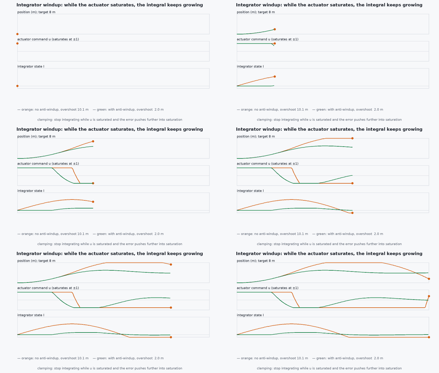
Think of as a spring, as a damper, and I as a slowly tightening bias that lifts the vehicle against a constant load such as wind or an off-centre battery. A spring alone oscillates; add damping to calm it; add an integrator to remove the remaining offset, but be gentle: an integrator is a source of lag and a classic cause of overshoot after saturation.
The key engineering rule: inner loops must be faster than outer loops, by a factor of roughly 3–10. An outer loop that tries to move faster than the inner loop can follow sees phase lag and oscillates. When a UAV “wobbles” slowly, the outer loop is too aggressive; when it buzzes, the inner derivative gain is too high or the signal is noisy.
Mathematical formulation
The PID law
Derivative on measurement with filtering
Differentiating a noisy measurement amplifies noise, and differentiating the error makes the output kick on every setpoint step. Use the derivative of the measurement, low-pass filtered with time constant (often with in 5–20):
Anti-windup
When the actuator saturates, the integrator keeps accumulating and then must be “unwound” after saturation ends, causing overshoot. Two standard fixes are clamping (stop integrating when saturated and the error would push further into saturation) and back-calculation (feed the saturation difference back into the integrator):
Attitude loop as an example
For the rotational plant with , a PD law gives , a second-order system with natural frequency and damping ratio . The Quadrotor Dynamics Simulator uses exactly this structure. Choose and within what the motors and their lag can deliver.
Architecture and data flow
In PX4 the cascade runs as separate modules (position and velocity control in the multicopter position controller; attitude and rate control in their own modules), each with its own parameters. The rate loop runs fastest on the main flight-controller loop; position loops run slower. Knowing where to look for each loop’s gains is the first debugging step: consult the PX4 multicopter PID tuning guide for the exact parameters of your version.
Real-world UAV applications
- Attitude and rate stabilisation in every multirotor autopilot.
- Altitude hold with barometer and accelerometer inputs.
- Gimbal and camera stabilisation.
- Baseline against which LQR and MPC results are judged (lessons M5-T7, M5-T8).
Implementation example
This runs as shown. A PID with filtered derivative-on-measurement and back-calculation anti-windup controls a double-integrator attitude plant with a torque limit. The test shows the windup problem and its fix.
import numpy as np

class PID:
    def __init__(self, kp, ki, kd, dt, umax, tau_f=0.02, kt=None):
        self.kp, self.ki, self.kd, self.dt, self.umax = kp, ki, kd, dt, umax
        self.alpha = tau_f / (tau_f + dt); self.d = 0.0; self.I = 0.0; self.y_prev = None
        self.kt = kt                                            # None: no anti-windup
    def __call__(self, r, y):
        e = r - y
        dy = 0.0 if self.y_prev is None else (y - self.y_prev) / self.dt
        self.y_prev = y
        self.d = self.alpha * self.d + (1 - self.alpha) * dy       # filtered derivative of the MEASUREMENT
        u = self.kp * e + self.I - self.kd * self.d
        u_sat = float(np.clip(u, -self.umax, self.umax))
        self.I += self.ki * self.dt * e
        if self.kt is not None: self.I += self.kt * self.dt * (u_sat - u)   # back-calculation
        return u_sat

def simulate(kt, step=1.0, T=8.0, dt=0.002, J=0.01, umax=0.06):
    pid = PID(kp=0.12, ki=0.15, kd=0.03, dt=dt, umax=umax, kt=kt)
    th = w = 0.0; hist = []
    for k in range(int(T / dt)):
        tau = pid(step if k * dt > 0.5 else 0.0, th)
        w += tau / J * dt; th += w * dt
        hist.append(th)
    hist = np.array(hist)
    return hist.max() / step - 1, abs(hist[-1] - step)

os_no, err_no = simulate(kt=None)
os_aw, err_aw = simulate(kt=1.0 / 0.05)
print(f"overshoot without anti-windup {100*os_no:.0f}%, with {100*os_aw:.0f}%; final error {err_no:.3f} / {err_aw:.3f} rad")
assert os_aw < os_no                                           # anti-windup reduces overshoot after saturation
assert err_aw < 0.05Common engineering mistakes
Integrating while saturated
Causes large overshoot after saturation; add anti-windup and report saturation to the controller.
Differentiating the error
A setpoint step becomes a huge derivative kick. Differentiate the measurement.
Unfiltered derivative on a noisy signal
Amplifies gyro noise and heats motors; low-pass the derivative.
Tuning the outer loop first
Tune from the inside out: rate, then attitude, then velocity, then position.
Ignoring plant changes
Mass and battery voltage change the effective gain; a tune that works at full battery oscillates at low battery or with payload.
Failure modes
| Failure mode | How it shows up | Likely cause |
|---|---|---|
| Slow oscillation (1–3 Hz) | Whole vehicle drifts back and forth | Position or velocity loop too aggressive for the attitude loop |
| Fast buzz | High-pitched vibration, hot motors | gain or rate-loop too high, noisy gyro or resonant frame |
| Overshoot after saturation | Large swing following a hard manoeuvre | Integrator windup |
| Steady-state offset in wind | Vehicle holds a few metres off target | No integral action or integrator limited too tightly |
Debugging approach
- Plot setpoint, measurement and output for each loop; look for ringing frequency to identify which loop is oscillating.
- Do step tests on one loop at a time with the outer loops open.
- Inspect the gyro spectrum for frame resonances and add notch filters if needed.
- Check that the log shows controller saturation flags and compare to integrator state.
Practical exercises
- Derive and for the PD attitude loop and choose gains for , .
- Remove derivative filtering in the code and measure the effect on output noise when the measurement has noise.
- Add a constant disturbance torque and show that the integral term removes the offset.
- Use the Quadrotor Dynamics Simulator to find Kp at which the attitude loop starts to oscillate with a 0.12 s motor time constant.
Interview questions
Write an answer in your own words, then reveal the model answer. Nothing is sent anywhere.
Question 1
Why are multirotor controllers cascaded, and what must hold between loops?
Model answer
The dynamics are a chain of integrators from torque to position, so each stage is controlled by a loop whose setpoint comes from the outer loop. Inner loops must be several times faster than the outer ones or phase lag makes the outer loop oscillate.
Question 2
What is integrator windup and how do you prevent it?
Model answer
The integral term keeps accumulating while the actuator is saturated and then overshoots when saturation ends. Prevent it by clamping the integrator or using back-calculation from the saturation difference.
Question 3
Why take the derivative of the measurement rather than the error?
Model answer
A setpoint step would create an impulse in the derivative of the error (derivative kick); the measurement is smooth, so it avoids the kick while still providing damping.
References and further reading
Primary papers, official documentation and standards. Each claim above that is specific to a tool or version points here.
- PX4: Multicopter PID tuning guide
- . . Åström, . . Murray, Feedback Systems: An Introduction for Scientists and Engineers, Princeton University Press, 2008 (free online at fbswiki.org).
- ArduPilot Copter: Tuning