UAV Systems Engineering · Module 6
M6-T3: PX4 architecture
A request to “make the drone do X” flows through a defined pipeline of modules. Know the pipeline and you know where to look when it fails.
PX4 splits the problem into modules that exchange messages. Each has one job: estimate, control, allocate, manage modes, log. This modularity is what makes it possible to replace or inspect any step, and it is the map you use to debug any behaviour.
Learning objectives
After this lesson, you should be able to:
- Name the main PX4 modules in the multicopter control pipeline and what each outputs.
- Distinguish the flight stack from the middleware and operating-system layers.
- Trace a position setpoint from the navigator to motor outputs.
- Explain what the commander and navigator decide and where failsafes originate.
Conceptual explanation
Implementation-specific Module names (for example mc_pos_control, mc_att_control, mc_rate_control, control_allocator, commander, navigator, ekf2) follow recent PX4 releases. Older releases used mixers instead of the control allocator and some names have changed. Check the architecture page of the documentation for your release.
The PX4 documentation describes two layers:
- The flight stack: the estimation and control algorithms, the navigator and commander, and the drivers.
- The middleware: the uORB publish/subscribe bus, the MAVLink and DDS communication layers, the logger and the operating-system abstraction (NuttX on flight controllers, POSIX on a PC for simulation).
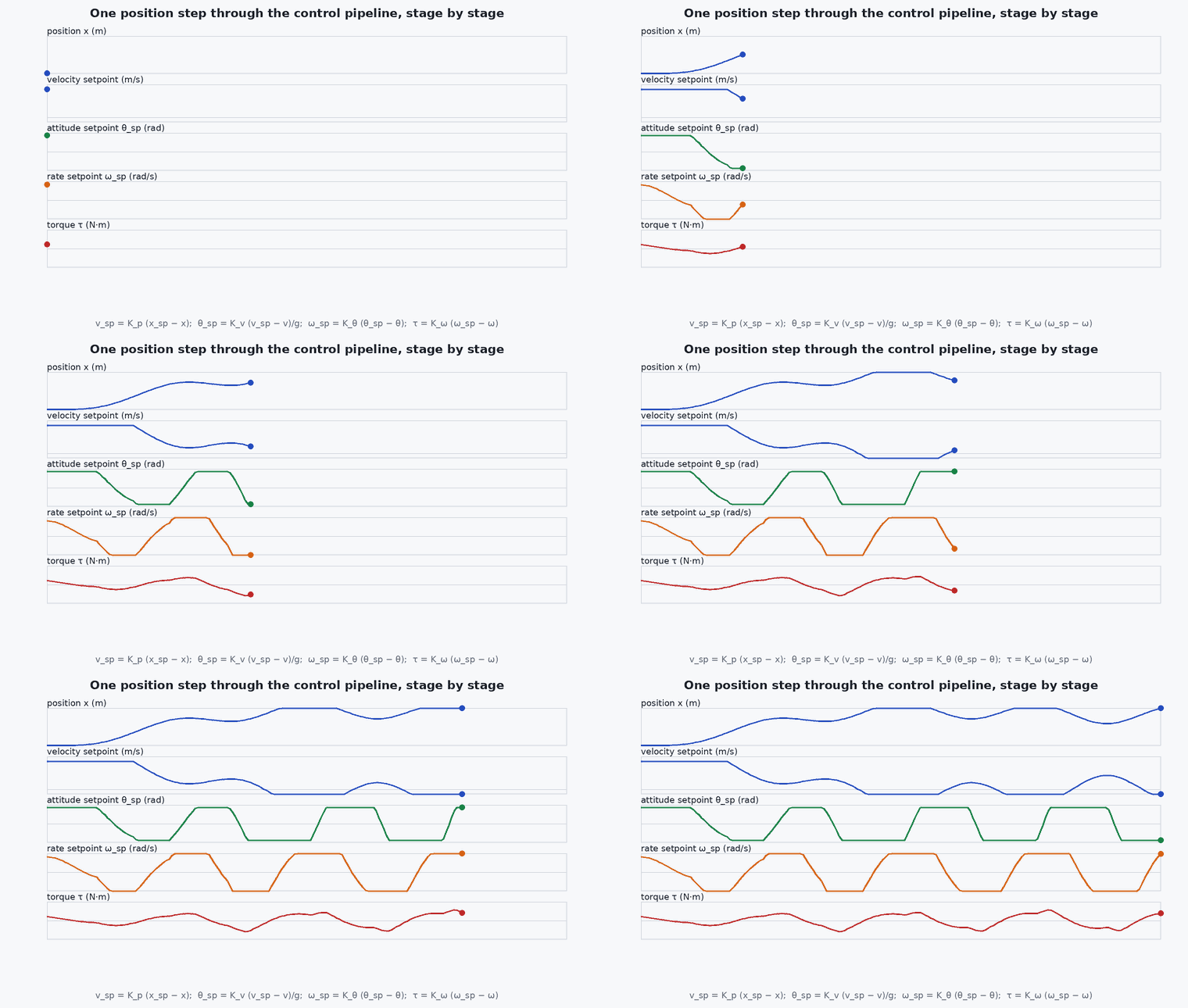
For a multicopter the control pipeline is a cascade of modules, each subscribing to the output of the previous one: mc_pos_control (position and velocity → attitude and thrust setpoint), mc_att_control (attitude → body-rate setpoint), mc_rate_control (rate → torque and thrust demand) and the control_allocator (demand → motor commands, respecting effectiveness and limits).
Engineering intuition
Picture an assembly line. Each station takes the previous station’s output, does one transformation, and hands it on. When the product at the end is wrong you inspect each hand-off: is the position setpoint what the navigator intended? Is the attitude setpoint consistent with it? Do the rate setpoints follow? Are the motor outputs saturated? Because every hand-off is a logged topic, you can answer these questions from a flight log.
The commander and navigator are the supervisors: the commander decides arming state, the active flight mode and failsafe actions from vehicle status, link health and sensor validity; the navigator produces the setpoints for mission, return and land modes. The controllers do not know why they are following a setpoint, only that they are.
Mathematical formulation
The cascade corresponds to the control design of the control lessons. In symbols, with the position error and velocity error , the position controller outputs an acceleration (and from it the thrust vector and attitude setpoint), the attitude controller outputs a rate setpoint from the attitude error, and the rate controller outputs torque :
The control allocator solves for actuator commands such that with the effectiveness matrix of the vehicle, subject to actuator limits; when limits are hit it reduces the lower-priority components (priorities follow the documentation of the version in use). The bandwidth separation of the earlier lesson applies stage by stage.
Architecture and data flow
Sensors (SPI/I²C/UART drivers) → sensor_combined, vehicle_gps_position → ekf2 → vehicle_local_position, vehicle_attitude, vehicle_odometry → mc_pos_control → vehicle_attitude_setpoint → mc_att_control → vehicle_rates_setpoint → mc_rate_control → vehicle_torque_setpoint, vehicle_thrust_setpoint → control_allocator → actuator_motors → output drivers. The navigator publishes position_setpoint_triplet and the trajectory setpoint, and the commander publishes vehicle_status and vehicle_control_mode. Topic names follow recent releases; list them with uorb top on your vehicle.
Real-world UAV applications
- Locating the cause of a tracking problem by comparing setpoints and measurements stage by stage.
- Replacing one stage, for example sending attitude or rate setpoints from a research controller.
- Adding a custom module that subscribes to estimator output and publishes diagnostic data.
- Writing the architecture section of a system design document.
Implementation example
Reading the pipeline from a flight log: load the topics named above with pyulog and compare each stage’s output with its input. This is a reference script (it needs a real .ulg file and pyulog, so the tests only check that it parses). Topic and field names follow recent releases.
from pyulog import ULog
import numpy as np

ulog = ULog('flight.ulg')
def topic(name):
    return next(d for d in ulog.data_list if d.name == name).data
pos = topic('vehicle_local_position'); att = topic('vehicle_attitude'); att_sp = topic('vehicle_attitude_setpoint')
t = pos['timestamp'] * 1e-6
print('estimator output rate: %.1f Hz' % (1.0 / np.median(np.diff(t))))
# tracking at the position level: reference is in the trajectory setpoint topic
try:
    sp = topic('trajectory_setpoint')
    n = min(len(sp['timestamp']), len(pos['timestamp']))
    err = np.hypot(sp['position[0]'][:n] - pos['x'][:n], sp['position[1]'][:n] - pos['y'][:n])
    print('median horizontal tracking error: %.2f m' % np.median(err))
except StopIteration:
print('no trajectory_setpoint topic in this log (mode without one)')Common engineering mistakes
Debugging at the wrong stage
Looking at motor outputs when the position setpoint was already wrong.
Assuming module names are stable
Older releases differ; read the version’s architecture page.
Editing parameters of several stages together
Change one stage at a time, from the inside out.
Ignoring the allocator
Motor saturation and effectiveness errors show up there, not in the controllers.
Confusing the commander’s mode with the controller’s setpoint source
A mode change changes which module supplies the setpoint, not the controllers themselves.
Failure modes
| Failure mode | How it shows up | Likely cause |
|---|---|---|
| Setpoint not followed | Tracking error large | A stage saturated, gains off, or the estimate wrong |
| Wrong motor mapping | Flip on takeoff | Motor order or direction misconfigured in the allocator/airframe settings |
| Unexpected mode change | Vehicle changes behaviour mid-flight | Failsafe action from the commander (link, battery, estimator) |
| Missing topic | Log lacks a stage | Logger topic selection (SDLOG parameters) excludes it |
Debugging approach
- Plot setpoint against measurement for each stage in the log.
- Check
vehicle_statusand failsafe flags at the time of the event. - Verify that the logged topic list includes all stages (logger profile).
- Compare actuator outputs against limits to find saturation.
Practical exercises
- Draw the pipeline for your PX4 version from the architecture documentation and mark every topic name.
- In SITL, use
listenerto print one message from each stage. - Find which parameter group configures each controller stage.
- In a flight log, find the time the commander changed the mode and list the topics that changed.
Interview questions
Write an answer in your own words, then reveal the model answer. Nothing is sent anywhere.
Question 1
Describe the multicopter control pipeline in PX4.
Model answer
Navigator or offboard setpoint → position/velocity controller (thrust vector and attitude setpoint) → attitude controller (rate setpoint) → rate controller (torque and thrust) → control allocator (motor commands), with EKF2 supplying the state.
Question 2
What is the role of the commander?
Model answer
It manages arming, flight modes and failsafes from vehicle status, link health and sensor validity, deciding which setpoint source is active and what to do when something fails.
Question 3
Why is a modular, message-based architecture useful for a research team?
Model answer
You can replace or tap any stage (for example inject external odometry or send rate setpoints), and every interface is a topic that can be logged and replayed.
References and further reading
Primary papers, official documentation and standards. Each claim above that is specific to a tool or version points here.