UAV Systems Engineering · Module 8
M8-T12: Visual odometry failure handling
Vision fails quietly: the estimate keeps coming but stops being true. Detect it with several indicators and have a bounded fallback.
Visual odometry rarely fails with an error. It fails with plausible numbers: a featureless wall, a sudden exposure change, motion blur, a repetitive texture or a moving crowd. A health monitor with independent indicators, a confidence level that drives mode changes, and an inertial fallback with a drift-based time limit turns a silent failure into a managed event.
Learning objectives
After this lesson, you should be able to:
- List the causes of VO failure and the signature each leaves in observable quantities.
- Design a multi-indicator health monitor with thresholds and hysteresis.
- Compute the time available in inertial fallback from the drift budget.
- Verify the monitor with fault injection and report detection delay and false alarms.
Conceptual explanation
Implementation-specific Indicators and thresholds are system-specific: the values in the example are placeholders to be tuned and validated for the actual camera, VIO algorithm and environment. VIO systems expose different diagnostics; check what yours provides.
Typical failure causes and how they appear:
| Cause | Signature | Indicator |
|---|---|---|
| Low texture (white wall, sky, dark corridor) | Few features, low corner quality | Tracked feature count falls; fewer well-distributed features |
| Motion blur, rolling shutter, rapid rotation | Features lost, tracking fails | Image sharpness metric; tracks per frame dropping |
| Exposure or lighting change | Brightness jump, saturation | Mean intensity and saturated pixel fraction |
| Repetitive texture / aliasing | Wrong matches that look consistent | Drop in inlier ratio, reprojection error up |
| Dynamic scene (people, vehicles) | Inconsistent motion between features | Inlier ratio down, estimated velocity disagrees with IMU |
| Camera fault, dropped frames, timing | Missing or late images | Frame rate and timestamp gaps |
The most informative single check is consistency with the inertial prediction: the VIO velocity or the visual position increment should agree with what the IMU predicts within the expected uncertainty. A normalised innovation (as in the EKF lesson) that stays high flags a failure that count-based indicators miss, such as wrong but consistent matches.
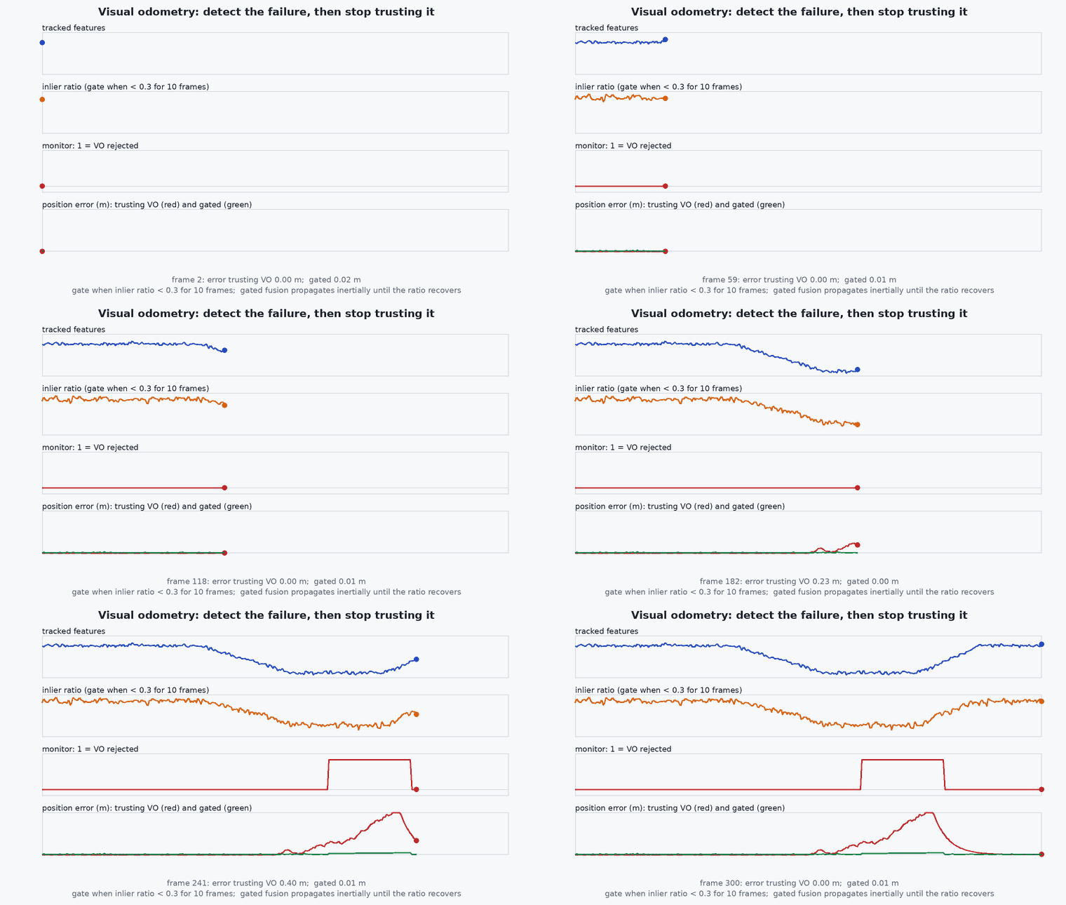
Engineering intuition
No single indicator is reliable: a high feature count on a repetitive pattern is dangerous, and a low count on a clean, well-conditioned scene may be fine. Combine indicators so that a failure shows up in at least two, and make the decision conservative in the direction of safety: enter degraded mode quickly, leave slowly (hysteresis).
The fallback time is an arithmetic fact: after vision is lost, the position error grows with the inertial drift. A velocity error grows position error linearly, and a constant accelerometer bias grows it as ½ . The bounded fallback is whichever limit the mission’s accuracy or clearance allows; when it is reached, the vehicle must already be doing something safe (hold in a known-safe place, land, or return on a path that is safe without precise position).
Mathematical formulation
Inertial dead-reckoning error after vision loss at time 0, with initial velocity error , accelerometer bias (after calibration), attitude error (which leaks gravity into horizontal acceleration as ) and velocity random walk :
The time to reach a drift budget is found by solving . With , (a modest tilt error and a small bias) and , ignoring noise: the vehicle has seconds, not minutes, which is why the safe action must start immediately. Detection delay counts against the same budget: with indicator confidence updated at frame rate and requiring consecutive bad frames, the delay is m/f; a combined delay of 0.3 s costs about ½·0.05·0.09 + 0.05·0.3 ≈ 0.017 m, small compared with the budget. The false-alarm rate is per window if bad frames are independent, which motivates .
- ,
- initial velocity and attitude errors at the moment of loss.
- residual accelerometer bias.
- velocity random walk of the accelerometer .
- allowed position drift budget.
Architecture and data flow
VIO front end diagnostics (tracked features, inliers, reprojection error) + image statistics (sharpness, mean intensity, saturated fraction, frame timestamps) + EKF innovations for the vision updates → health monitor → confidence level and reason code → flight controller (stop fusing external vision, change mode) and mission layer (slow down, hold, land). The decision, its reason and the indicators are logged at every change for post-flight analysis, and the dropout is reported to the operator.
Real-world UAV applications
- Handling featureless corridors and lighting changes in GNSS-denied flights.
- Deciding when to stop fusing visual odometry into the autopilot.
- Setting the time limit for inertial fallback in the mission plan.
- Fault-injection tests of the vision pipeline.
Implementation example
This runs as shown. A multi-indicator health monitor on a synthetic sequence with three injected faults: a featureless period, a repetitive-texture period (features present, but matches inconsistent with the IMU) and a blur burst. It reports detection delay per fault and false alarms in fault-free periods, and the fallback time budget from the drift formula.
import numpy as np
rng = np.random.default_rng(41)
fps, T = 20, 120; n = fps * T; t = np.arange(n) / fps
feat = 150 + 15 * rng.standard_normal(n); inl = 0.9 + 0.03 * rng.standard_normal(n); sharp = 1.0 + 0.05 * rng.standard_normal(n); nis = rng.chisquare(3, n) / 3     # fault-free indicators (nis: normalised innovation squared, mean 1)
def seg(a, b): return (t >= a) & (t < b)
f1, f2, f3 = seg(30, 38), seg(60, 70), seg(95, 99)
feat[f1] = 12 + 3 * rng.standard_normal(f1.sum())                                   # fault 1: featureless wall: few features
inl[f2] = 0.45 + 0.05 * rng.standard_normal(f2.sum()); nis[f2] = 9 + 2 * rng.standard_normal(f2.sum())      # fault 2: repetitive texture: features fine, inliers and consistency bad
sharp[f3] = 0.35 + 0.05 * rng.standard_normal(f3.sum()); feat[f3] = 40 + 8 * rng.standard_normal(f3.sum())  # fault 3: blur burst
def bad(i):
    flags = [feat[i] < 60, inl[i] < 0.7, sharp[i] < 0.6, nis[i] > 5.0]
    return sum(flags) >= 1 and (sum(flags) >= 2 or feat[i] < 30 or nis[i] > 5.0)          # at least one strong indicator, or two weak ones
state = 'good'; bad_run = 0; good_run = 0; events = []
for i in range(n):
    if bad(i): bad_run += 1; good_run = 0
    else: good_run += 1; bad_run = 0
    if state == 'good' and bad_run >= 3: state = 'lost'; events.append((t[i], 'lost'))
    elif state == 'lost' and good_run >= 20: state = 'good'; events.append((t[i], 'good'))   # leave slowly: 1 s of clean frames
for name, f in (('featureless', f1), ('repetitive', f2), ('blur', f3)):
    start = t[f][0]; det = next((te for te, s in events if s == 'lost' and te >= start), None)
    print(f"{name:>11}: starts at {start:5.1f} s, declared lost at {det:5.2f} s (delay {det - start:.2f} s)")
fa = [te for te, s in events if s == 'lost' and not (f1 | f2 | f3)[min(int(te * fps), n - 1)] and not (f1 | f2 | f3)[max(int(te * fps) - 5, 0)]]
print("false alarms in fault-free periods:", len(fa))
assert len(fa) == 0 and all(next(te for te, s in events if s == 'lost' and te >= t[f][0]) - t[f][0] < 0.5 for f in (f1, f2, f3))
v0, bg, D = 0.05, 0.05, 2.0; tt = np.sqrt(2 * D / bg) if v0 == 0 else (-v0 + np.sqrt(v0 ** 2 + 2 * bg * D)) / bg
print(f"inertial fallback time to reach {D} m of drift (v0 = {v0} m/s, bias-equivalent {bg} m/s^2): {tt:.1f} s")
assert 6 < tt < 9Common engineering mistakes
Trusting feature count alone
Repetitive textures give many consistent-looking but wrong matches; add consistency with the IMU.
Symmetric thresholds
Leave degraded mode more slowly than you enter it.
Unlimited inertial fallback
Position error grows quadratically; bound the time and act.
No logging of the reason
Without the indicator values you cannot tune the thresholds after the flight.
Testing only in the lab
Real failure causes (sunlight, dust, crowds) are not in the lab.
Failure modes
| Failure mode | How it shows up | Likely cause |
|---|---|---|
| Silent drift | Vehicle drifts while estimates look normal | Monitor relies on a single indicator that did not trip |
| Flapping between modes | Repeated degrade and recover | No hysteresis or too tight thresholds |
| Late reaction | Large excursion before the safe action | Detection plus action time not budgeted against drift |
| False alarms in good conditions | Unnecessary fallbacks | Thresholds set on one environment |
Debugging approach
- Plot every indicator with the ground-truth failure intervals and the monitor’s decision.
- Compute detection delay and false-alarm rate on recorded data.
- Check innovation consistency against the IMU independently of the VIO’s own confidence.
- Replay failure recordings through the monitor offline after each change.
Practical exercises
- Tune the thresholds on a recording of your own VIO and report detection delay and false alarms.
- Compute the fallback time for and a 0.2 m/s initial velocity error.
- Add an exposure-saturation indicator and a test with a flashlight.
- Write the mode-transition table for the VO confidence levels with the autopilot’s modes.
Interview questions
Write an answer in your own words, then reveal the model answer. Nothing is sent anywhere.
Question 1
Why is a single VO health indicator not enough?
Model answer
Different failures show in different indicators: a repetitive texture keeps the feature count high while the matches are wrong, and a clean low-texture scene can have few features but fine tracking; combine indicators and add consistency with the inertial prediction.
Question 2
How long can you fly on inertial navigation after VO is lost?
Model answer
Until position error from velocity error, bias and attitude error (growing roughly quadratically) reaches the drift budget, typically seconds to a few tens of seconds for a small vehicle, so the safe action must start at detection.
Question 3
What is hysteresis for in a health monitor?
Model answer
It prevents flapping: the system enters degraded mode quickly on a few bad frames and leaves only after a sustained period of good ones.
References and further reading
Primary papers, official documentation and standards. Each claim above that is specific to a tool or version points here.
- Forster, C., Carlone, L., Dellaert, F. & Scaramuzza, D. (2017). On-manifold preintegration for real-time visual-inertial odometry. IEEE T-RO 33(1)
- Mur-Artal, R. & Tardós, J. D. (2017). ORB-SLAM2: an open-source SLAM system for monocular, stereo and RGB-D cameras. IEEE T-RO 33(5)
- PX4: Visual inertial odometry (VIO)