UAV Systems Engineering · Module 7
M7-T8: Camera, IMU and LiDAR synchronization
Fusion assumes every measurement is stamped with the time the world was sampled. A few milliseconds of error look like sensor noise and cost accuracy that no filter can recover.
A camera and an IMU on a moving UAV are two clocks watching the same motion. If the clocks disagree, the filter fuses measurements of different instants. This lesson shows how large the effect is, how to avoid it by design, and how to measure the offset you cannot avoid.
Learning objectives
After this lesson, you should be able to:
- Explain clock offset, drift and latency, and the effect of a timing error on fusion.
- Compare hardware triggering, PTP and software timestamping.
- Estimate a camera-IMU time offset from data using cross-correlation.
- State the metrics that show a synchronisation problem in a log.
Conceptual explanation
Implementation-specific Achievable timing accuracy depends on the sensor hardware, interfaces and drivers; use the figures in your sensors’ documentation rather than assuming typical values.
Each sensor stamps data with its clock, or the host stamps data on arrival. Three effects separate the stamp from the true sampling time: a constant offset between clocks, a slowly varying drift (clock frequency error), and latency between sampling and stamping (exposure, transfer, driver buffering). A fused estimate needs all three understood.
| Approach | How | Strength | Limit |
|---|---|---|---|
| Hardware trigger | The autopilot or a microcontroller pulses the camera, and the pulse time is logged against the IMU clock | Sub-millisecond, deterministic | Needs hardware support and wiring |
| PTP / hardware time sync | Clocks disciplined over Ethernet (IEEE 1588) | Sub-microsecond to microsecond on suitable hardware | Needs PTP-capable NICs and sensors |
| Software timestamps | Host stamps on arrival, optionally corrected for known latency | No hardware needed | Includes transfer and scheduling jitter; typically milliseconds |
Engineering intuition
Motion makes timing visible: if the vehicle rotates at 90°/s, a 10 ms error between the camera and the IMU means a orientation mismatch, which a VIO filter may interpret as bias or extrinsic error. If the vehicle translates at 5 m/s, 10 ms is 5 cm. Slow flight hides the problem and fast flight exposes it, which is why a system that works in a gentle test can fail in a real mission.
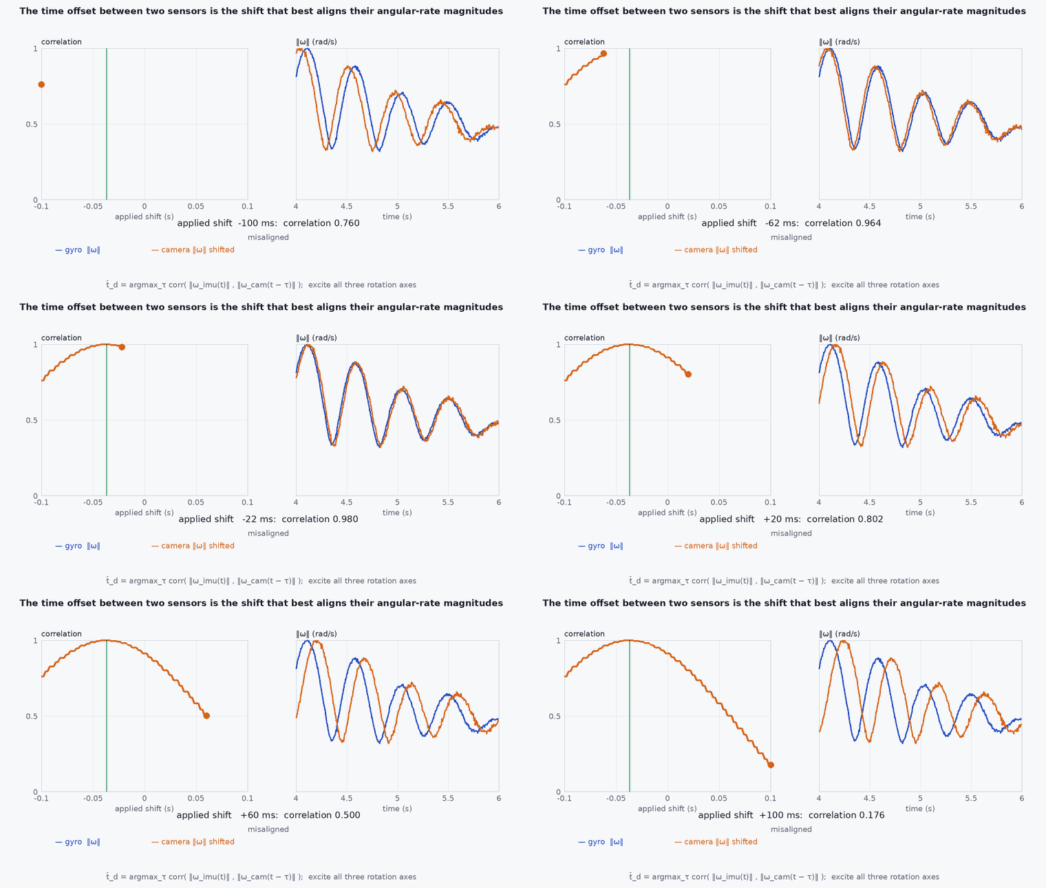
A constant offset can be estimated, because the same motion is seen by both sensors: the gyro measures angular rate directly, and the camera estimates it from images. Slide one signal against the other and the best overlap gives the offset. VIO systems such as VINS-Fusion and OpenVINS can also estimate the camera-IMU time offset online as part of the state, which works well for a small constant offset but not for jitter.
Mathematical formulation
Effects of a time error for angular rate and speed :
Offset estimation by cross-correlation of two sampled signals a(t), (t):
The resolution of the integer-sample estimate is the sampling interval; a parabolic fit around the peak gives sub-sample resolution. The excitation must contain rotation changes: a constant rotation rate has no unique alignment. The estimate also includes any constant processing latency, which is exactly what is wanted for fusion.
Architecture and data flow
For a camera and IMU: both stamped on the same clock (trigger-based) → driver forwards the trigger time as the image stamp (not the arrival time) → VIO fuses with a residual offset parameter. For a LiDAR: PTP or a GNSS PPS signal disciplines the LiDAR clock, and per-point timestamps allow undistortion (lesson M4-T8). Always forward the original acquisition stamp; never overwrite it with the host’s time.
Real-world UAV applications
- Camera-IMU calibration: estimating the time offset together with the extrinsic transform (for example with Kalibr).
- Choosing between a trigger wire and software timestamps for a new payload.
- Diagnosing VIO that degrades only at high rotation rates.
- LiDAR-IMU alignment for FAST-LIO2-style systems.
Implementation example
This runs as shown: it simulates gyro measurements and an image-derived angular rate with a known 23 ms offset and noise, and recovers the offset by cross-correlation with sub-sample refinement.
import numpy as np
rng = np.random.default_rng(5)
fs = 200.0; dt = 1 / fs; T = 30.0; t = np.arange(0, T, dt)
omega = 0.8 * np.sin(2 * np.pi * 0.35 * t) + 0.5 * np.sin(2 * np.pi * 0.9 * t + 1.0) + 0.3 * np.sin(2 * np.pi * 1.7 * t + 2.0)   # rad/s, a varied rotation
true_offset = 0.023                                              # camera clock lags the IMU clock by 23 ms
gyro = omega + 0.02 * rng.standard_normal(len(t))
cam = np.interp(t - true_offset, t, omega, left=0.0) + 0.05 * rng.standard_normal(len(t))        # same rotation, delayed and noisier

def estimate_offset(a, b, dt, max_lag=0.2):
    a = a - a.mean(); b = b - b.mean()
    lags = np.arange(-int(max_lag / dt), int(max_lag / dt) + 1)
    r = np.array([np.dot(a[max(0, -l): len(a) - max(0, l)], b[max(0, l): len(b) - max(0, -l)]) for l in lags])
    k = int(np.argmax(r))
    if 0 < k < len(r) - 1:                                       # parabolic refinement around the peak
        y0, y1, y2 = r[k - 1], r[k], r[k + 1]
        k = k + 0.5 * (y0 - y2) / (y0 - 2 * y1 + y2)
    return (np.interp(k, np.arange(len(lags)), lags)) * dt

est = estimate_offset(gyro, cam, dt)
print(f"true offset {1000 * true_offset:.1f} ms, estimated {1000 * est:.2f} ms")
assert abs(est - true_offset) < 0.0015 # within 1.5 ms (a fraction of a 5 ms sample)Common engineering mistakes
Stamping with arrival time and calling it synchronised
Arrival includes exposure, transfer and scheduling: milliseconds that vary.
Estimating the offset from a slow, smooth motion
No excitation, no unique alignment. Include varied rotations in the calibration data.
Assuming constant offset when the clock drifts
Over long flights, drift accumulates: measure it or use disciplined clocks.
Calibrating once on the bench
Offset can change with exposure time, USB hub, CPU load or driver version: re-check after any change.
Hiding timing errors by inflating IMU noise
It masks the cause and hurts accuracy.
Failure modes
| Failure mode | How it shows up | Likely cause |
|---|---|---|
| Rotation-dependent drift in VIO | Estimate fine when slow, drifts when yawing quickly | Time offset between camera and IMU |
| Smeared LiDAR map in turns | Double walls | IMU–LiDAR offset or missing per-point times |
| Offset that changes between flights | Calibration does not transfer | Exposure-dependent camera latency or non-deterministic driver |
| Sudden VIO divergence after a USB event | Frames arrive late in bursts | Transport jitter on a shared bus |
Debugging approach
- Log both stamps (sensor and arrival) for every message and plot their difference over time.
- Run the offset estimator on several flights and look at its spread: large spread means jitter, not a constant offset.
- Check that the autopilot’s trigger timestamps are used as image stamps.
- Compare angular rates from gyro and from visual rotation estimates on the same plot, before fusion.
Practical exercises
- Compute the position error from a 15 ms offset at 6 m/s.
- Run the example with the offset of −40 ms and with only a slow sinusoidal rotation; explain the difference in accuracy.
- Add clock drift of 50 ppm and estimate how the offset changes over 10 minutes.
- Explain how a hardware trigger measures image time against the IMU clock.
Interview questions
Write an answer in your own words, then reveal the model answer. Nothing is sent anywhere.
Question 1
Why does a few-millisecond camera-IMU offset matter?
Model answer
Fusion assumes simultaneous measurements; at rotation rate and speed , a error is of orientation and of position, which filters mistake for bias or extrinsic error. It matters most in fast motion.
Question 2
How can a camera-IMU time offset be estimated?
Model answer
Compare the gyro rate with the angular rate derived from images and find the shift that maximises their correlation, or estimate it online within VIO. It needs varied rotation to excite both sensors.
Question 3
Hardware trigger versus software timestamp?
Model answer
A hardware trigger gives deterministic, sub-millisecond image times on the IMU clock; software timestamps include transfer and scheduling jitter of milliseconds.
References and further reading
Primary papers, official documentation and standards. Each claim above that is specific to a tool or version points here.