UAV Systems Engineering · Module 7
M7-T9: Hardware triggering
If the exposure is started by a pulse you control, you know when the image was taken to within the pulse latency, whatever the USB or CSI driver does afterwards.
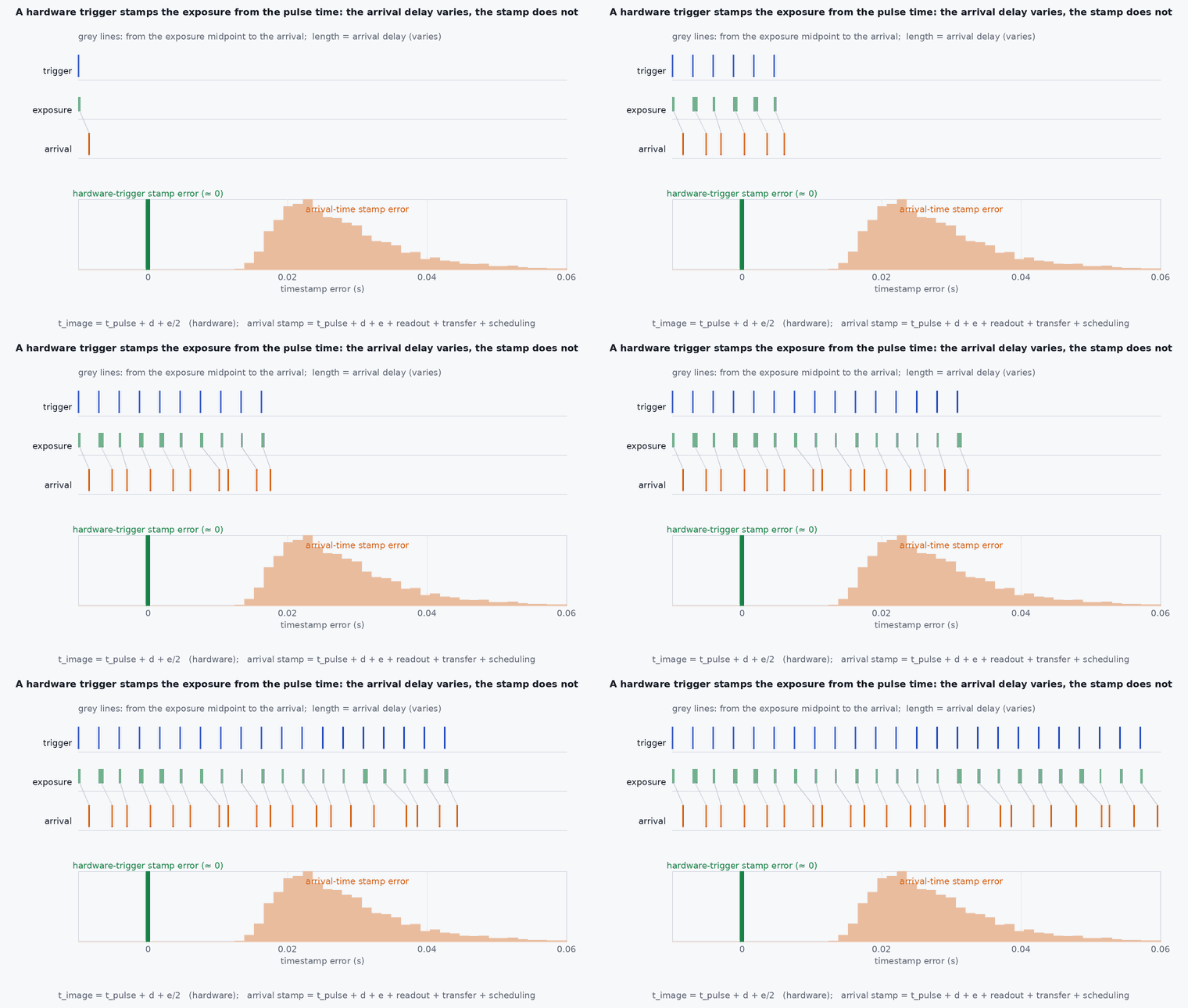
Software timestamps record when an image arrived, which can be tens of milliseconds after it was taken, with a varying delay. A hardware trigger replaces that guess with a measurement: the pulse that starts the exposure is time-stamped on the same clock as the IMU. This is the most reliable way to get camera-IMU synchronisation for VIO.
Learning objectives
After this lesson, you should be able to:
- Describe the hardware trigger chain and where its remaining timing errors come from.
- Compute the image timestamp at the exposure midpoint from the pulse time and exposure time.
- Match triggered images to trigger events robustly, including dropped frames.
- Verify synchronisation by measuring residual offset from data.
Conceptual explanation
Implementation-specific Trigger and feedback interfaces depend on the camera, the flight controller and the PX4 release (PX4 provides a camera trigger module with TRIG_* parameters and a camera capture feedback mechanism). Camera trigger inputs and exposure behaviour differ by model: read the camera’s datasheet and test it.
In a hardware-triggered setup the camera exposes only when it receives a pulse (or at a rate locked to a pulse train). The trigger source records the pulse time on the vehicle’s clock, typically the same clock that stamps the IMU, using a hardware timer input capture so that interrupt latency does not enter. Each pulse has a sequence number, and so does each image (a frame counter in the metadata or a count of received frames).
- Image timestamp: the time the sensor was exposed, taken at the middle of the exposure for a global shutter: , where is the camera’s fixed delay from pulse to exposure start (from the datasheet or measured).
- Rolling shutter: each row is exposed at a different time; the timestamp refers to a reference row (usually the middle one) and the readout time per row must be modelled or estimated.
- Matching: by sequence number, with a check that the interval between consecutive images equals the interval between pulses; dropped frames show as gaps in the image sequence but not in the pulse log.
Engineering intuition
Think of a photographer’s flash popping at a known instant: you note the time when you fired it, and you do not need to look at your watch when the photo reaches your computer. The arrival time of an image includes exposure, readout, transfer, driver and scheduling delays, each of which varies. The pulse time includes only a small, fixed latency.
Two practical worries remain. First, the camera may take a fixed delay from pulse to exposure start that you must know (a few tens of microseconds to some milliseconds depending on the model): measure it with an LED flashing on a known schedule if the datasheet is unclear. Second, auto-exposure changes from frame to frame, so if the timestamp is the exposure midpoint, the exposure time must be read from the image metadata for every frame.
Mathematical formulation
With pulse time on the IMU clock, a fixed pulse-to-exposure delay , and exposure time , the midpoint timestamp is
If the trigger rate is , the pulse times are with timer quantisation error of order one timer tick (1 µs on a 1 MHz timer). For a camera-IMU system moving with angular rate , a timestamp error causes an orientation inconsistency of ; for and this is 5 mrad, about , which at a focal length of 500 px is 2.5 px of image shift at the periphery, comparable to the reprojection noise of a good tracker. The error in the camera-IMU time offset, if left uncalibrated, also appears in the visual-inertial estimator as spurious bias and scale error, which is why the offset is often estimated online as well (see the calibration lessons).
- ,
- time of pulse on the IMU clock.
- fixed delay from pulse to start of exposure.
- exposure time of frame .
- ,
- angular rate and timestamp error.
Architecture and data flow
Flight controller timer → trigger output pin → camera trigger input; the same timer captures the pulse timestamp on its clock → published as a trigger/capture message (PX4 camera trigger feedback) with sequence number → companion computer receives it over MAVLink or DDS (with the vehicle-to-companion clock offset applied, see time synchronisation) → image driver supplies the frame with a frame counter → the matcher joins them → the image message header receives the corrected stamp → VIO. The clock relation between flight controller and companion must itself be estimated, which adds its own error.
Real-world UAV applications
- VIO and lidar-visual fusion needing sub-millisecond camera-IMU alignment.
- Photogrammetry geotagging: each image tagged with the position at the trigger time.
- Multi-camera rigs triggered from a single pulse for simultaneous capture.
- Calibrating the camera-IMU time offset against a known trigger.
Implementation example
This runs as shown. A synthetic triggered camera at 20 Hz: images arrive with a variable delay and some are dropped. The matcher uses sequence numbers (taken from a frame counter that wraps) to attach pulse times; the test measures the timestamp error against the true exposure midpoint and compares it with arrival-time stamping.
import numpy as np
rng = np.random.default_rng(8)
f, n = 20.0, 400
t_pulse = np.arange(n) / f + 0.00001 * rng.standard_normal(n)                  # pulse times captured on the IMU clock (about 10 us quantisation noise)
d_trig = 0.0004; exp = rng.uniform(0.002, 0.012, n)                              # fixed pulse-to-exposure delay; auto-exposure changes the exposure time
t_true = t_pulse + d_trig + exp / 2                                             # true exposure midpoint (what the stamp should be)
arrival = t_pulse + d_trig + exp + 0.012 + rng.gamma(2.0, 0.006, n)             # arrival after readout, USB transfer and scheduling (variable)
dropped = rng.random(n) < 0.03
frames = [(k % 256, arrival[k], exp[k]) for k in range(n) if not dropped[k]]    # 8-bit wrapping frame counter

# match by sequence number, handling the wrap by unrolling against the pulse count
stamps = {}; last_k = -1
for cnt, arr, e in frames:
    base = (last_k // 256) * 256; k = base + cnt
    if k <= last_k: k += 256                                                     # counter wrapped
    last_k = k; stamps[k] = t_pulse[k] + d_trig + e / 2
err_hw = np.array([stamps[k] - t_true[k] for k in stamps]); err_arr = np.array([arrival[k] - t_true[k] for k in stamps])
print(f"matched {len(stamps)} of {n} frames; hardware-trigger stamp error rms {np.sqrt(np.mean(err_hw ** 2)) * 1e6:.2f} us; arrival stamp error mean {err_arr.mean() * 1e3:.1f} ms, std {err_arr.std() * 1e3:.1f} ms")
assert np.sqrt(np.mean(err_hw ** 2)) < 1e-9 and err_arr.mean() > 0.02
w, dt_err = 1.0, 0.005; print(f"orientation inconsistency for {dt_err * 1e3:.0f} ms at {w} rad/s: {np.degrees(w * dt_err):.2f} deg")Common engineering mistakes
Stamping at arrival time
Delays of tens of ms with jitter; use the pulse time.
Ignoring auto-exposure
Midpoint changes with exposure time; read it per frame or fix the exposure.
Unknown pulse-to-exposure delay
A constant offset that VIO will mis-attribute to other errors: measure it.
Matching by arrival order
A dropped frame shifts all later matches; use counters.
Different clocks for pulse and IMU
The point of the trigger is lost; capture the pulse on the IMU clock.
Failure modes
| Failure mode | How it shows up | Likely cause |
|---|---|---|
| Constant time offset | VIO scale or bias wrong; tracking unstable at fast rotation | Unmodelled pulse-to-exposure delay or half-exposure |
| Misalignment after a dropped frame | Stamps off by one frame | Matching by order instead of sequence |
| Jitter in stamps | Noise in VIO | Pulse captured by software, not a timer capture |
| No trigger feedback | Trigger times unavailable | Feedback messages not enabled or lost on the link |
Debugging approach
- Flash an LED on the trigger schedule and check which frame shows it to measure the delay.
- Plot the interval between image stamps: it should equal the trigger interval.
- Plot the difference between arrival and trigger times to see the transfer-delay distribution.
- Check the frame counter for gaps and wraps.
Practical exercises
- Compute the image shift in pixels at the periphery for a 3 ms timestamp error at 2 rad/s and focal length 600 px.
- Add rolling-shutter readout (10 µs per row, 720 rows) and compute the stamp for the middle row.
- Design the matcher so that it recovers after a 5 s gap in the image stream.
- Describe the test that measures for a camera of your choice.
Interview questions
Write an answer in your own words, then reveal the model answer. Nothing is sent anywhere.
Question 1
Why is a hardware trigger better than timestamping on arrival?
Model answer
The pulse time is measured on the IMU clock with microsecond-level latency, while arrival includes exposure, readout, transfer, driver and scheduling delays that are large and variable.
Question 2
Where should the image timestamp point within the exposure?
Model answer
At the exposure midpoint for a global shutter (and a reference row for a rolling shutter), so the stamp is the time the scene was effectively sampled.
Question 3
How do you match triggered images to pulses when frames may be dropped?
Model answer
By sequence number or frame counter (unwrapped), never by order, and check the image interval against the pulse interval.
References and further reading
Primary papers, official documentation and standards. Each claim above that is specific to a tool or version points here.