UAV Systems Engineering · Module 1
M1-T9: Companion computer architecture
The flight controller keeps the vehicle in the air; the companion computer decides where to go. Keeping them separate is a safety decision.
Perception and planning need a general-purpose computer with a GPU and a full operating system; flight control needs determinism and a short, auditable code path. Putting them on different processors is how modern UAVs keep the vehicle flying when the clever software crashes.
Learning objectives
After this lesson, you should be able to:
- Explain the split of functions between flight controller and companion computer.
- Estimate the data rates crossing the boundary and choose an interface.
- Describe watchdogs and the behaviour on companion failure.
- List the power, thermal and mounting concerns of a companion computer.
Conceptual explanation
The flight controller (FC) is a microcontroller running a real-time operating system: IMU sampling, estimation, attitude and rate control, motor outputs, failsafes. The companion computer is a Linux machine (for example a Jetson-class module) running ROS 2, perception, SLAM, planning and logging. They exchange a small amount of control-critical data (state, setpoints, commands) and the FC never depends on the companion to stay airborne.
Engineering intuition
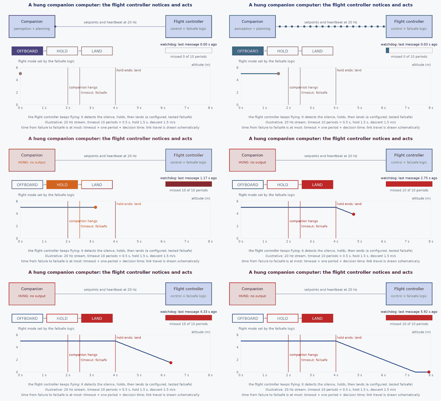
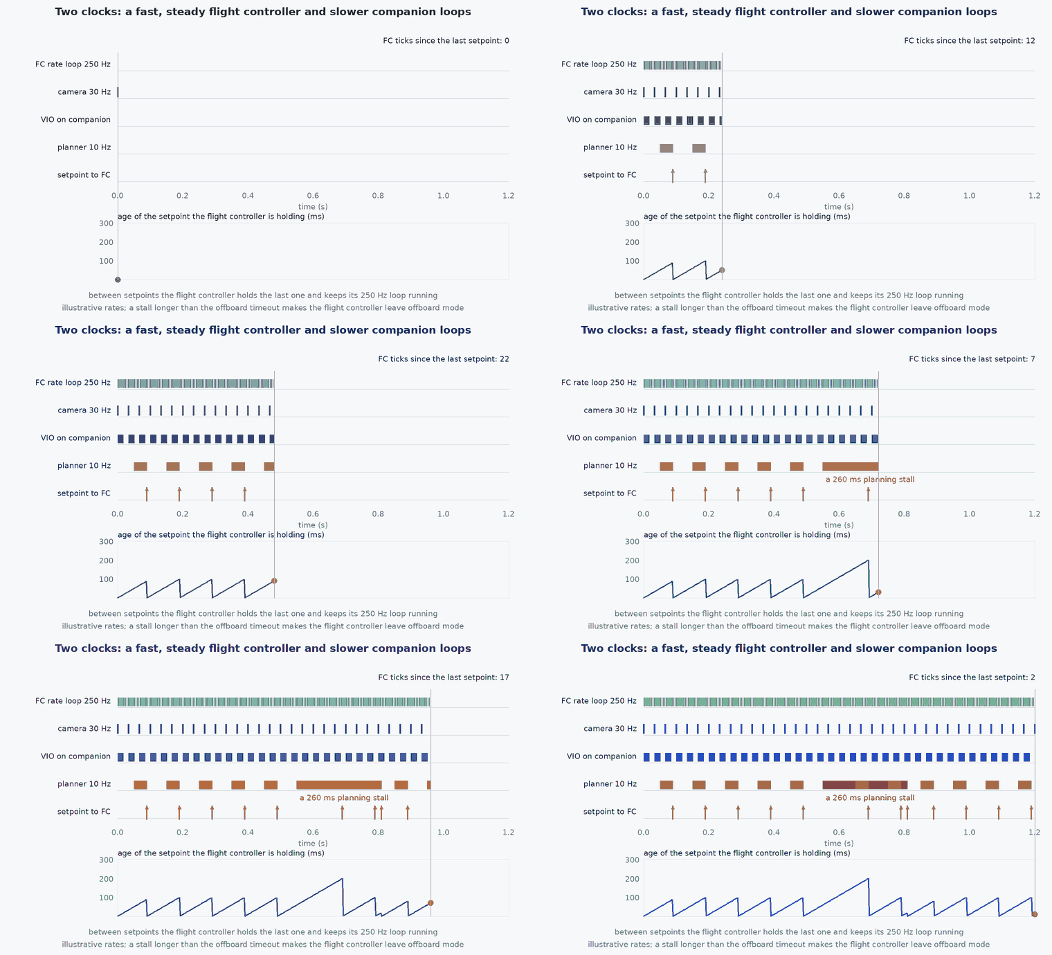
Ask what happens when each side crashes. If the companion hangs, the FC must notice (the offboard setpoint stream stops; lesson M6-T11) and execute a failsafe: hold, return or land. If the FC fails, the vehicle is lost whatever the companion does, so the FC should be simple, tested and conservative. This asymmetry decides the split: anything whose failure must not cause a crash lives on the FC; anything that may fail safely lives on the companion.
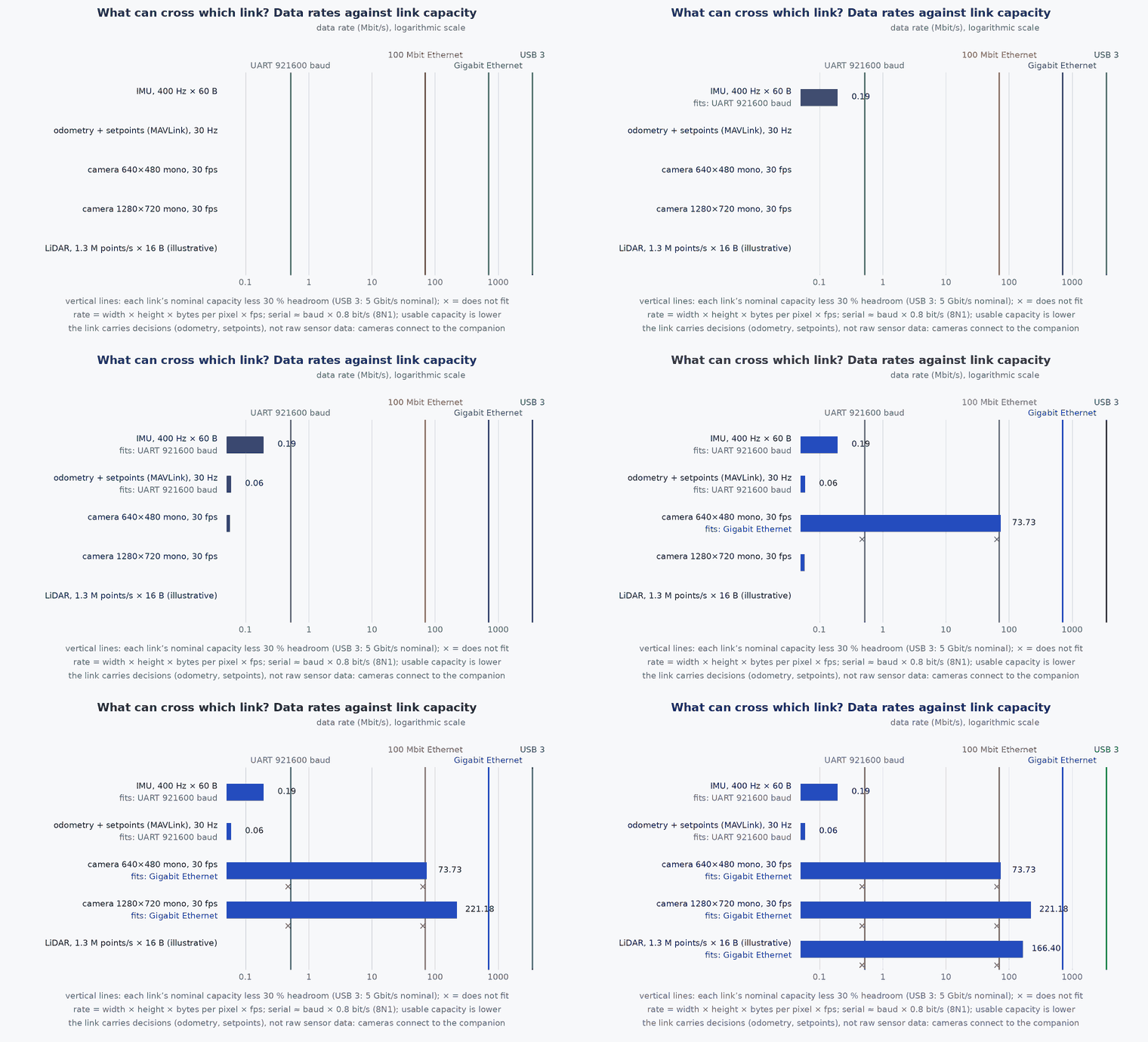
The link should carry decisions (setpoints, odometry) not raw sensor data. A camera produces tens of megabytes per second; the control link carries kilobytes.
Mathematical formulation
Raw data rates determine what can cross which interface:
A serial link at baud rate carries at most about b/10 bytes per second (8 data bits plus start and stop). At 921600 baud that is about 92 kB/s, shared by all MAVLink or uXRCE-DDS traffic: enough for odometry and setpoints, nowhere near enough for images. Uncompressed 720p30 mono video (221 Mbit/s) does not fit 100 Mbit/s Ethernet and needs gigabit Ethernet, USB 3 or MIPI CSI, which is why cameras connect straight to the companion and never to the flight controller.
Power: the companion often draws more than the entire avionics stack; a budget in watts per mode (lesson M7-T13) decides the regulator, the cooling and the flight time lost to carrying it.
Architecture and data flow
Typical interfaces: companion ↔ FC over a UART (MAVLink or uXRCE-DDS) or Ethernet; cameras to the companion over MIPI CSI, USB or Ethernet; LiDAR over Ethernet; time synchronisation via PPS or PTP (lesson M7-T11). The odometry bridge converts frames and timestamps before data enter EKF2 (lesson M6-T10).
Real-world UAV applications
- Running ROS 2 perception and planning without touching the flight code.
- Isolating research software from a certified or tested flight stack.
- Hot-swapping autonomy software between flights without reflashing the autopilot.
- Containing failures: a crashed planner becomes a hold, not a crash.
Implementation example
This runs as shown: a bandwidth budget of the boundary and sensor links, flagging what does not fit the interface chosen.
def image_rate_Bps(w, h, bytes_pp, fps): return w * h * bytes_pp * fps
def serial_capacity_Bps(baud): return baud / 10.0

links = {"UART 921600": serial_capacity_Bps(921600), "UART 3 Mbaud": serial_capacity_Bps(3_000_000), "Ethernet 100M": 100e6 / 8 * 0.9, "Ethernet 1G": 1e9 / 8 * 0.9}
flows = {
    "odometry 50 Hz (100 B)": 100 * 50,
    "setpoints 50 Hz (80 B)": 80 * 50,
    "telemetry (all topics, est.)": 30_000,
    "mono camera 1280x720 30 fps": image_rate_Bps(1280, 720, 1, 30),
    "LiDAR points (est. 300 kB/s)": 300_000,
}
control = flows["odometry 50 Hz (100 B)"] + flows["setpoints 50 Hz (80 B)"] + flows["telemetry (all topics, est.)"]
for name, cap in links.items():
    print(f"{name}: control traffic uses {100 * control / cap:.0f}% of capacity; camera fits: {flows['mono camera 1280x720 30 fps'] < cap}")
assert control < 0.5 * links["UART 921600"]                       # the control traffic fits on a 921600-baud link with margin
assert flows["mono camera 1280x720 30 fps"] > links["UART 3 Mbaud"] and flows["mono camera 1280x720 30 fps"] > links["Ethernet 100M"] and flows["mono camera 1280x720 30 fps"] < links["Ethernet 1G"]
assert abs(flows["mono camera 1280x720 30 fps"] - 27_648_000) < 1Common engineering mistakes
Running safety-critical control on the companion
A Linux process can be delayed or killed; keep the control loop on the FC.
Sending raw sensor data over the control link
Starves control traffic; process on the companion and send decisions.
Single shared power rail for FC and companion
A companion current spike browns out the FC; isolate and filter.
No heartbeat or watchdog
A dead side is not detected; use heartbeats both ways and a hardware watchdog on the companion.
Treating USB 3 as harmless
USB 3 emits broadband noise that can desensitise nearby GNSS receivers.
Failure modes
| Failure mode | How it shows up | Likely cause |
|---|---|---|
| Companion crash in flight | Setpoints stop; vehicle exits offboard | Software fault or overheating; failsafe must be configured |
| Link saturated | Stale state on the companion, rising latency | Too many topics or raw data on the link |
| GNSS degradation after payload install | Satellite count drops when the companion boots | USB 3 or switching-supply noise near the antenna |
| Brown-out reset | Companion reboots on motor transients | Shared rail without regulation |
Debugging approach
- Measure link utilisation and per-topic rates.
- Pull the companion’s power in a tethered test and check the FC failsafe.
- Compare GNSS satellite count and C/N0 with the companion off and on.
- Log both sides’ heartbeat timestamps.
Practical exercises
- Compute the bandwidth of a 640×480 camera at 60 fps and decide the interface.
- List which functions of your design must stay on the FC if the companion may crash.
- Design a heartbeat with a timeout so that one lost message does not trigger a failsafe.
- Estimate the mass penalty of the companion plus its extra battery for a 20 minute flight.
Interview questions
Write an answer in your own words, then reveal the model answer. Nothing is sent anywhere.
Question 1
Why separate the flight controller and the companion computer?
Model answer
Different requirements: real-time determinism and a small auditable code path for control, versus general-purpose compute and a full OS for perception; separation lets the vehicle survive a companion crash.
Question 2
What should cross the boundary?
Model answer
State, setpoints, commands and odometry: small, low-rate, control-critical data; not raw sensor streams.
Question 3
What happens when the companion fails in flight?
Model answer
The FC detects the lost heartbeat or setpoint stream and executes the configured failsafe such as hold, return or land.
References and further reading
Primary papers, official documentation and standards. Each claim above that is specific to a tool or version points here.