UAV Systems Engineering · Module 7
M7-T1: UAV onboard computing architecture
Where a function runs decides its latency, its determinism and what its failure can take down with it.
A UAV is a distributed computer with a weight and power limit. Deciding where each function runs is the first architecture decision, and it is driven by three questions: how fast and how predictably must it respond, how much compute does it need, and what happens to the vehicle if it fails.
Learning objectives
After this lesson, you should be able to:
- Partition UAV functions between the flight controller, companion computer and ground station using explicit criteria.
- Explain the role of failure containment and a narrow interface between safety-critical and best-effort software.
- Estimate whether a function’s latency and compute needs fit the chosen processor.
- Document the partition so that it can be reviewed and changed.
Conceptual explanation
Established This is standard embedded-systems and safety-architecture practice. The example numbers in the table are order-of-magnitude illustrations of typical systems, not specifications of any product.
Three processor classes appear on most research and commercial UAVs:
| Class | Typical hardware | Strength | Weakness |
|---|---|---|---|
| Real-time microcontroller (flight controller) | Cortex-M class MCU running an RTOS | Deterministic timing, low power, small, robust | Limited compute and memory |
| Application processor (companion CPU) | Multi-core ARM or x86 running Linux | Flexible software, ROS, networking, large memory | Non-deterministic scheduling, boot time, more failure modes |
| Accelerator (GPU, NPU, FPGA, vision DSP) | Embedded GPU or dedicated accelerator | High throughput for vision, learning, mapping | Power, heat, driver and memory-copy complexity |
Partition by three criteria:
- Latency and determinism: loops with deadlines of a few milliseconds and tight jitter (rate control, attitude control, state estimation with the IMU) belong on the real-time microcontroller.
- Compute and memory: perception, mapping, VIO front ends, learning-based methods and global planning need more than a microcontroller can supply and belong on the companion.
- Failure containment: anything whose failure must not endanger the vehicle sits behind an interface the flight controller can supervise: a companion crash must degrade to a defined safe state, not take the stabilisation down.
Engineering intuition
Think of two organisations: an operations room that must never stop (the flight controller) and a research team that can be brilliant and occasionally wrong (the companion). The operations room accepts requests from the research team through a formal channel, checks them, and keeps working if the team goes quiet. Putting a critical function in the research team, or giving the research team unfiltered control, puts the flight at the mercy of a general-purpose operating system.
The placement is not permanent: a function can move as it matures. Visual-inertial odometry typically starts on the companion; if it must run when the companion is unavailable, it has to be moved, simplified or duplicated. Move the function, and the failure analysis moves with it.
Mathematical formulation
A simple feasibility test for placing a function on a processor: the worst-case execution time and the period must satisfy the utilisation bound with margin, and the end-to-end latency must fit the budget:
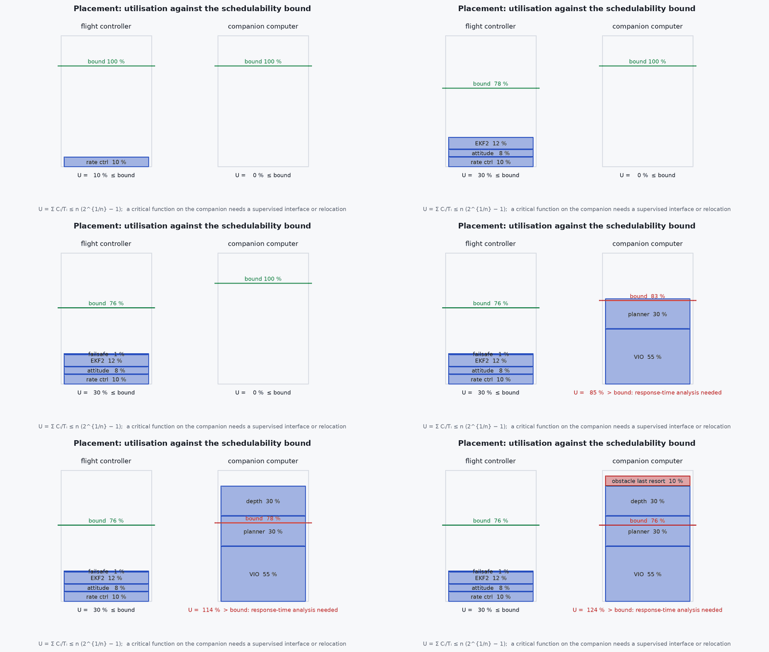
For a set of periodic tasks under rate-monotonic fixed-priority scheduling a sufficient utilisation bound for tasks is , which tends to for large and is 0.828 for and 0.780 for . Above that bound schedulability must be shown by response-time analysis. Failure containment can be quantified by the probability that a companion fault affects the vehicle: with rate of companion faults and detection coverage of the supervisor, the rate of uncontained events is , which is why coverage of the heartbeat and output checks matters as much as the companion’s own reliability.
- ,
- worst-case execution time and period of task .
- processor utilisation.
- coverage: fraction of companion faults detected and contained by the supervisor.
Architecture and data flow
Sensors → flight controller (IMU, barometer, GNSS, magnetometer) → estimator and controllers → actuators. Camera, lidar and depth sensors → companion (CPU and GPU) → perception, VIO, mapping, planning → narrow command interface (offboard setpoints or external odometry) → flight controller supervision (stream monitoring, plausibility limits) → controllers. State and status flow back from the flight controller to the companion. Telemetry and video go to the ground.
Real-world UAV applications
- Choosing where VIO or lidar odometry runs for a GNSS-denied vehicle.
- Deciding whether obstacle avoidance’s last-resort layer runs on the flight controller or the companion.
- Sizing the companion computer from the perception pipeline.
- Writing the system architecture section of a design review.
Implementation example
This runs as shown. A placement checker: each function has a period, worst-case execution time, a latency deadline and a criticality; the checker computes the utilisation per processor with the rate-monotonic bound and flags violations such as a safety-critical function placed on the companion.
import numpy as np
funcs = [  # name, period s, WCET s (measured on that processor), deadline s, safety-critical?, processor
    ('rate control', 0.004, 0.0004, 0.004, True, 'fc'), ('attitude control', 0.004, 0.0003, 0.004, True, 'fc'),
    ('ekf2', 0.010, 0.0012, 0.010, True, 'fc'), ('failsafe monitor', 0.020, 0.0002, 0.020, True, 'fc'),
    ('vio frontend', 0.033, 0.018, 0.100, False, 'companion'), ('planner', 0.100, 0.030, 0.200, False, 'companion'),
    ('depth fusion', 0.067, 0.020, 0.150, False, 'companion'), ('obstacle last resort', 0.020, 0.002, 0.060, True, 'companion')]
def rm_bound(n): return n * (2 ** (1.0 / n) - 1)
problems = []
for proc in ('fc', 'companion'):
    fs = [f for f in funcs if f[5] == proc]; U = sum(f[2] / f[1] for f in fs)
    print(f"{proc}: {len(fs)} tasks, utilisation {U:.2f}, RM bound {rm_bound(len(fs)):.2f}")
    if U > rm_bound(len(fs)): problems.append(f"{proc}: utilisation above the sufficient bound (needs response-time analysis)")
for f in funcs:
    if f[2] > f[3]: problems.append(f"{f[0]}: WCET exceeds deadline")
    if f[4] and f[5] == 'companion': problems.append(f"{f[0]}: safety-critical function placed on the companion (needs a supervised interface or relocation)")
for p in problems: print("PROBLEM:", p)
assert abs(rm_bound(2) - 0.8284) < 1e-3 and abs(rm_bound(3) - 0.7798) < 1e-3
assert any('obstacle last resort' in p for p in problems)Common engineering mistakes
Putting the last-resort safety function on the planner’s processor
If the planner stalls, so does the safety net.
Unmeasured execution times
Estimates of WCET are usually optimistic; measure on the target under load.
A wide, unmonitored interface
The more authority crosses the interface, the more must be checked.
No plan for the companion’s failure
Define the flight controller’s action; test it.
Ignoring accelerator memory copies
Moving frames between CPU and GPU memory can dominate the latency.
Failure modes
| Failure mode | How it shows up | Likely cause |
|---|---|---|
| Companion crash grounds or crashes the vehicle | Loss of control after a software fault | Safety function depends on the companion; no supervisor |
| Missed deadlines at high load | Jitter in control | Utilisation too high, shared cores, priority inversion |
| Latency spikes | Occasional long delays | Garbage collection, swap, throttling, contention on the accelerator |
| Interface overload | Dropped messages | Bandwidth or rate beyond the link |
Debugging approach
- Measure execution time distributions per function on the target under realistic load.
- Trace the data path timestamps end to end.
- Disable the companion in a bench test and check the flight controller’s response.
- Review each function’s placement against the three criteria.
Practical exercises
- Place twelve functions of your own vehicle on processors and justify each by the three criteria.
- Compute the rate-monotonic bound for 5 tasks and compare it to the measured utilisation.
- Define the interface between the companion and the flight controller: messages, rates, limits, timeouts.
- Estimate the fault rate that escapes containment with coverage 0.9 and 0.99 for a companion fault rate of per hour.
Interview questions
Write an answer in your own words, then reveal the model answer. Nothing is sent anywhere.
Question 1
How do you decide what runs on the flight controller versus the companion?
Model answer
By latency and determinism needs, compute needs and failure containment: hard-real-time and safety-critical loops stay on the microcontroller, heavy perception and planning go to the companion behind a narrow, monitored interface.
Question 2
Why is a utilisation bound only a sufficient condition?
Model answer
The rate-monotonic bound guarantees schedulability below it, but task sets above it can still be schedulable; response-time analysis settles it.
Question 3
What is failure containment?
Model answer
Designing so that a fault in one part does not propagate: the flight controller supervises the companion’s outputs and heartbeat and degrades to a safe state if they fail.
References and further reading
Primary papers, official documentation and standards. Each claim above that is specific to a tool or version points here.