UAV Systems Engineering · Module 6
M6-T10: External vision and odometry integration
Give PX4 a position it can trust from somewhere other than GNSS: get the frames, the timestamps and the covariance right, then set the parameters.
This is the integration that turns a research-grade VIO or LIO into a flying system: the autopilot’s own estimator accepts the companion computer’s odometry as a measurement. The interface is small, and nearly every failure comes from the same three details.
Learning objectives
After this lesson, you should be able to:
- Explain what EKF2 expects in a VehicleOdometry message and where it is published.
- Convert an ENU/FLU odometry message into the NED/FRD message PX4 expects.
- Set the timestamp, variances and quality fields correctly.
- Name the EKF2 parameters that control external-vision fusion and verify fusion in the logs.
Conceptual explanation
Implementation-specific Parameter names and defaults below are those of recent PX4 releases (v1.14 and later) as documented by PX4. They change between versions: read the “external position estimation” and EKF2 pages for your version before flying.
PX4’s EKF2 can fuse position, velocity and yaw from an external vision or odometry source. Over uXRCE-DDS the companion computer publishes a px4_msgs/VehicleOdometry message on /fmu/in/vehicle_visual_odometry (over MAVLink the equivalent messages are ODOMETRY and VISION_POSITION_ESTIMATE). EKF2 then treats it like any other measurement: it gates it by innovation, weights it by the supplied variances (or by fixed parameters), and uses it to correct the IMU-propagated state.
Engineering intuition
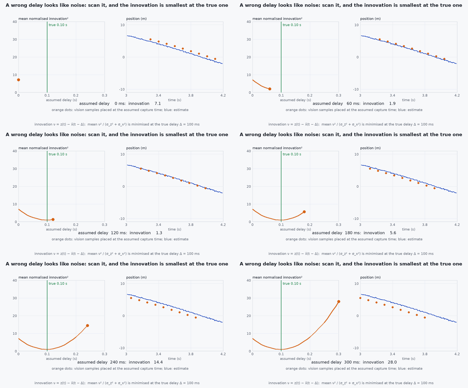
There are three things EKF2 cannot know and you must tell it. Frame: is this NED/FRD or an arbitrary frame? A wrong frame yields a mirrored or rotated trajectory. Time: when was the measurement taken? Vision pipelines have 30–100 ms of latency; if the message is stamped with “now” instead of the exposure time, EKF2 corrects the wrong state and the error looks like random jitter. Trust: how uncertain is it? A VIO that reports a tiny, constant variance after tracking is lost will drag the estimate off with high confidence.
Mathematical formulation
Position and velocity convert as in lesson M1-T4. For the orientation quaternion, the rotation from FLU to ENU must become the rotation from FRD to NED. With qENU←FLU and the fixed frame rotations QNED←ENU and QFRD←FLU:
Latency compensation: the measurement refers to the state at time (exposure), but arrives at . EKF2 keeps a short history of its states; given the sample time (timestamp_sample) or the delay parameter, it fuses the measurement against the state at and corrects forward. Without the true sample time, the estimator’s effective measurement error includes : at 5 m/s with 80 ms of unmodelled delay that is 0.4 m.
Parameters (check your PX4 version)
| Parameter | What it does |
|---|---|
| EKF2_EV_CTRL | Bitmask enabling which external-vision quantities are fused: horizontal position, vertical position, velocity, yaw. |
| EKF2_HGT_REF | Selects the height source (barometer, GNSS, range sensor or vision). |
| EKF2_GPS_CTRL | Bitmask for GNSS fusion; set to 0 to disable GNSS fusion for a GNSS-denied configuration (older releases used EKF2_AID_MASK). |
| EKF2_EV_DELAY | Delay of the vision measurement relative to the IMU if the sample time is not provided. |
| EKF2_EV_NOISE_MD | Choose between the variances in the message and fixed noise parameters (EKF2_EVP_NOISE, EKF2_EVV_NOISE, EKF2_EVA_NOISE). |
Checking the orientation conversion
The quaternion conversion is the easiest part to get wrong and the easiest to test without a vehicle. This runs as shown: a level vehicle facing east in ENU must become a yaw in NED/FRD, and one facing north must become zero yaw.
import numpy as np

def qmul(a, b):
    w1, x1, y1, z1 = a; w2, x2, y2, z2 = b
    return np.array([w1*w2 - x1*x2 - y1*y2 - z1*z2, w1*x2 + x1*w2 + y1*z2 - z1*y2,
                     w1*y2 - x1*z2 + y1*w2 + z1*x2, w1*z2 + x1*y2 - y1*x2 + z1*w2])

S = np.sqrt(0.5)
Q_NED_ENU = np.array([0.0, S, S, 0.0]); Q_FRD_FLU = np.array([0.0, 1.0, 0.0, 0.0])
def enu_flu_to_ned_frd(q): return qmul(qmul(Q_NED_ENU, q), Q_FRD_FLU)

def yaw_of(q):                                    # yaw (rotation about the down axis) of a level quaternion [w, x, y, z]
    return np.degrees(np.arctan2(2 * (q[0] * q[3] + q[1] * q[2]), 1 - 2 * (q[2] ** 2 + q[3] ** 2)))

east = np.array([1.0, 0, 0, 0])                                              # ENU yaw 0: facing east
north = np.array([np.cos(np.pi / 4), 0, 0, np.sin(np.pi / 4)])               # ENU yaw +90 deg (ccw from east): facing north
print("facing east -> NED yaw", round(yaw_of(enu_flu_to_ned_frd(east)), 3), "deg; facing north ->", round(yaw_of(enu_flu_to_ned_frd(north)), 3), "deg")
assert abs(abs(yaw_of(enu_flu_to_ned_frd(east))) - 90) < 1e-9 and abs(yaw_of(enu_flu_to_ned_frd(north))) < 1e-9
assert abs(np.linalg.norm(enu_flu_to_ned_frd(east)) - 1) < 1e-12Architecture and data flow
VIO produces a pose with covariance at camera rate → the bridge converts frames and fills timestamp (publication time, microseconds) and timestamp_sample (acquisition time), pose_frame and velocity_frame, position, q, velocity, the variance arrays and quality → /fmu/in/vehicle_visual_odometry → EKF2. Unknown quantities should be set to NaN, not zero: zero means “exactly zero”. Verify in the flight log that vision fusion is active and that innovations are small (lesson M6-T13).
Real-world UAV applications
- GNSS-denied navigation indoors with VIO or LiDAR-inertial odometry.
- Motion-capture position input for lab flights.
- Position hold using external odometry in tunnels and warehouses.
- Simulation of the whole chain in SITL with a simulated odometry source before flying.
Implementation example
A minimal bridge node (syntax-checked here, not executed by the tests: it needs ROS 2 and px4_msgs). It converts an ENU/FLU nav_msgs/Odometry to the NED/FRD VehicleOdometry. Verify field names and constants against the px4_msgs version you build.
import numpy as np, rclpy
from rclpy.node import Node
from rclpy.qos import QoSProfile, ReliabilityPolicy, DurabilityPolicy, HistoryPolicy
from nav_msgs.msg import Odometry
from px4_msgs.msg import VehicleOdometry

def qmul(a, b):                                   # Hamilton product, [w, x, y, z]
    w1, x1, y1, z1 = a; w2, x2, y2, z2 = b
    return np.array([w1*w2 - x1*x2 - y1*y2 - z1*z2, w1*x2 + x1*w2 + y1*z2 - z1*y2,
                     w1*y2 - x1*z2 + y1*w2 + z1*x2, w1*z2 + x1*y2 - y1*x2 + z1*w2])

S = np.sqrt(0.5)
Q_NED_ENU = np.array([0.0, S, S, 0.0])            # 180 deg about (1,1,0)/sqrt(2): ENU -> NED
Q_FRD_FLU = np.array([0.0, 1.0, 0.0, 0.0])        # 180 deg about x: FLU -> FRD

class VioToPx4(Node):
    def __init__(self):
        super().__init__('vio_to_px4')
        qos = QoSProfile(reliability=ReliabilityPolicy.BEST_EFFORT, durability=DurabilityPolicy.TRANSIENT_LOCAL,
                         history=HistoryPolicy.KEEP_LAST, depth=1)
        self.pub = self.create_publisher(VehicleOdometry, '/fmu/in/vehicle_visual_odometry', qos)
        self.create_subscription(Odometry, '/vio/odometry', self.cb, 10)

    def cb(self, m: Odometry):
        o = VehicleOdometry()
        stamp_us = m.header.stamp.sec * 1_000_000 + m.header.stamp.nanosec // 1000     # sample time of the data
        o.timestamp = int(self.get_clock().now().nanoseconds // 1000)                  # publication time (see note below)
        o.timestamp_sample = stamp_us      # NOTE: ROS time and the autopilot clock must be synchronised, or convert with a measured offset
        o.pose_frame = VehicleOdometry.POSE_FRAME_FRD   # check the constant in your px4_msgs version
        p = m.pose.pose.position
        o.position = [float(p.y), float(p.x), float(-p.z)]                             # ENU -> NED
        q = m.pose.pose.orientation
        qn = qmul(qmul(Q_NED_ENU, np.array([q.w, q.x, q.y, q.z])), Q_FRD_FLU)          # q_NED<-FRD
        o.q = [float(v) for v in qn]
        cov = np.array(m.pose.covariance).reshape(6, 6)
        o.position_variance = [float(cov[1, 1]), float(cov[0, 0]), float(cov[2, 2])]   # N, E, D variances
        nan3 = [float('nan')] * 3; o.velocity = nan3; o.angular_velocity = nan3         # unknown: NaN, not zero
        self.pub.publish(o)

rclpy.init(); rclpy.spin(VioToPx4())Common engineering mistakes
Publishing with the arrival time instead of the sample time
EKF2 fuses against the wrong state: the symptom is jitter proportional to speed.
Reporting constant, optimistic covariance
After tracking loss the filter trusts a wrong pose; publish honest variances and raise them on degraded tracking.
Zero instead of NaN for unknown fields
Zero velocity is a claim, not an absence of data.
Leaving GNSS fusion enabled while testing GNSS-denied behaviour
EKF2 keeps using GNSS: the test proves nothing. Disable it with the right parameter and verify in the log.
Mismatched heading between vision and magnetometer
Two yaw sources fighting each other cause slow rotation; choose the yaw source deliberately.
Failure modes
| Failure mode | How it shows up | Likely cause |
|---|---|---|
| Mirrored or rotated trajectory | Vehicle flies the wrong way when commanded | ENU/FLU vs NED/FRD or yaw convention error |
| Position jitter proportional to speed | Hover is fine, motion is shaky | Wrong or missing sample timestamp |
| EKF2 rejects vision | Log shows repeated innovation failures; vehicle falls back to other sources | Variances too small, large frame error or divergence of the VIO |
| Height drift | Altitude walks away | Vertical position not fused or conflicting height sources |
Debugging approach
- Plot the vision position beside EKF2’s local position in the log: they should differ by a fixed transform only.
- Look at the estimator innovation test ratios and fusion flags (see the log-analysis lesson) to confirm vision is being accepted.
- Compare the message timestamps with the autopilot clock to measure latency and offset.
- Test the bridge in SITL with a simulated odometry source before any real flight.
Practical exercises
- Derive QNED←ENU as the quaternion of a rotation about and check it in code.
- Compute the position error from a 60 ms unmodelled delay at 8 m/s.
- Decide the EKF2_EV_CTRL bits for a vehicle that should use vision horizontal position and yaw but barometer height.
- Write a test that feeds a known ENU pose and asserts the NED values.
Interview questions
Write an answer in your own words, then reveal the model answer. Nothing is sent anywhere.
Question 1
What must you set correctly in a VehicleOdometry message for EKF2?
Model answer
The frame (NED/FRD), the sample timestamp (acquisition time), honest variances, and NaN for unknown fields.
Question 2
Why does a wrong timestamp make estimates jitter with speed?
Model answer
The measurement is fused against the wrong past state, so the error is roughly speed times the timing error, which grows with velocity.
Question 3
How do you test GNSS-denied behaviour safely?
Model answer
In SITL first, with GNSS fusion disabled via the EKF2 parameters, an external odometry source, and the logs checked to confirm that only vision is used.
References and further reading
Primary papers, official documentation and standards. Each claim above that is specific to a tool or version points here.