UAV Systems Engineering · Module 6
M6-T1: Introduction to PX4
PX4 is the real-time core of many research and commercial UAVs. Know what it does, what it leaves to you, and how to read its documentation.
Most UAV autonomy projects do not write a flight controller; they sit on top of one. PX4 is a widely used open-source autopilot with a modular flight stack. Knowing its boundaries (what it guarantees, what it expects from you) is the first step to integrating it safely.
Learning objectives
After this lesson, you should be able to:
- Describe what PX4 does and which functions it leaves to external software.
- Place PX4 between hardware, middleware and the companion computer.
- Explain the release model and why documentation versions matter.
- Run the standard first checks on a PX4 vehicle: version, parameters, logs and sensors.
Conceptual explanation
Implementation-specific This lesson describes PX4 as documented at the time of writing. PX4 evolves quickly: module names, parameters, message definitions and defaults change between releases. Always read the documentation for the exact version you fly (the PX4 guide has a version selector).
PX4 is an open-source flight control software stack for drones and other uncrewed vehicles (multicopters, fixed-wing, VTOL, rovers). It is developed in the open under a permissive BSD licence and is hosted by the Dronecode Foundation. It runs on a microcontroller-class flight controller, normally on the NuttX real-time operating system, and can also run on a desktop for simulation (software-in-the-loop).
The stack does four jobs:
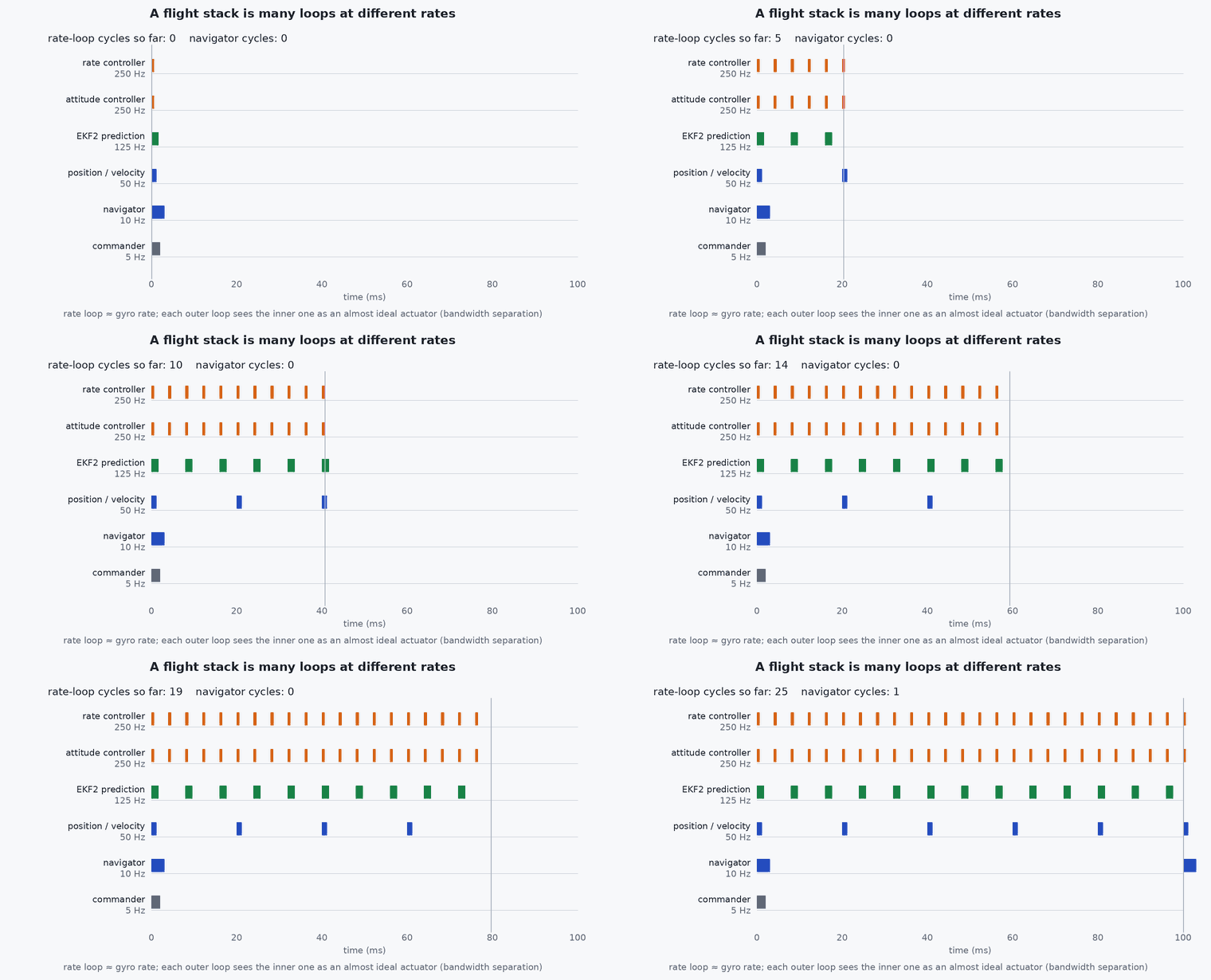
- Sensing and estimation: drivers read the IMU, barometer, magnetometer and GNSS, and the EKF2 estimator produces position, velocity and attitude.
- Control: a cascade of position, velocity, attitude and rate controllers produces torque and thrust demands, and a control allocator turns these into actuator outputs.
- Mode management and safety: the commander module handles arming, flight modes and failsafes; the navigator handles missions, return and landing.
- Communication: MAVLink to ground stations and companions, and a DDS bridge for ROS 2.
Engineering intuition
Think of PX4 as the “spinal cord” of the vehicle: fast reflexes, stabilisation and safety, running at hundreds of hertz on dedicated hardware where timing is predictable. The companion computer is the “brain”: perception, planning and learning, running on a general-purpose OS where timing varies. The split is deliberate: a crashed planner must not take the stabilisation loop down with it, which is why offboard control has a heartbeat and failsafes.
A second intuition is that PX4 is a framework with opinions. It already provides state estimation, tuned controllers, calibration and logging; when you replace one piece (for example feeding it external odometry) you are working inside its assumptions about frames, timestamps and covariances.
Mathematical formulation
There is little new mathematics here; the stack uses the estimation and control methods of the earlier modules. Two quantities help in budgeting and debugging. The cascaded loop rates give the time-scale separation (typical orders of magnitude, version- and vehicle-dependent):
| Loop | Typical rate | Role |
|---|---|---|
| Rate controller | hundreds of Hz to ~1 kHz (follows the gyro rate) | torque from body-rate error |
| Attitude controller | ~250 Hz or the gyro rate | rate setpoint from attitude error |
| Velocity/position controller | ~50–100 Hz | thrust vector from velocity/position error |
| EKF2 | ~100 Hz output with IMU-driven prediction | state estimate |
| Navigator / commander | a few Hz to tens of Hz | mode logic, mission |
The rates above are indicative: check the module configuration for your release. The pipeline latency from sensor to motor is the sum of sampling, filtering, estimation, control and actuator delays; it constrains how aggressive the tuning can be (see the guidance-and-control integration lesson).
Architecture and data flow
Inside PX4 everything is connected by uORB (a publish/subscribe message bus): sensor drivers publish sensor_combined, EKF2 publishes vehicle_local_position and vehicle_attitude, controllers publish setpoints, the control allocator publishes actuator outputs. Outside, MAVLink carries telemetry and commands to ground stations; the uXRCE-DDS client exposes selected uORB topics to ROS 2. This is why it is easy to log everything and inspect any internal signal: the topics are the data flow.
Real-world UAV applications
- Research platforms that add custom perception and planning on a companion computer.
- Commercial inspection, mapping and delivery vehicles built on PX4-compatible flight controllers.
- Simulation-driven development: the same stack runs in SITL and on hardware.
- Education: a readable reference implementation of a UAV stack.
Implementation example
First checks on any PX4 system, run from the PX4 console (MAVLink shell or serial console). Command names are stable but outputs differ by version; this block is shown for reference and is not run by the tests.
ver all                       # firmware version, git hash, board
param show EKF2_*             # estimator parameters
listener vehicle_status       # one message from a uORB topic
listener vehicle_local_position
uorb top                      # topic publication rates
top                           # CPU load per task (NuttX)
dmesg                         # boot messages, driver errors
logger status # is the flight log being written?Read the ver all output into your test report: the exact firmware, hash and board are part of the configuration baseline (see the configuration-management lesson).
Common engineering mistakes
Reading the documentation of the wrong version
The default “main” documentation may describe features your stable release does not have.
Treating default parameters as tuned for your vehicle
Defaults are generic; frame, propellers and battery change the right values.
Replacing a module without understanding its contract
The estimator and controllers expect specific frames, units and rates.
Not logging
Without a flight log, a crash cannot be investigated; confirm logging is on and the card works.
Flying a custom build without recording its hash
No reproducibility; no way to say what was flown.
Failure modes
| Failure mode | How it shows up | Likely cause |
|---|---|---|
| Will not arm | Pre-arm check failures | Calibration, sensors, GNSS lock, safety switch, battery, mode requirements |
| Unstable in first hover | Oscillation | Wrong frame configuration, motor order or propeller direction, untuned gains |
| Estimator failures in flight | EKF2 resets or failsafe | Vibration, magnetic interference, bad GNSS or vision input |
| Documentation mismatch | A parameter does not exist | Reading a different version than the firmware |
Debugging approach
- Record firmware version and hash with every flight.
- Use the logger and Flight Review to see estimator and controller behaviour.
- Use
listeneranduorb topto see what each module publishes. - Change one parameter at a time and keep a parameter diff.
Practical exercises
- List the PX4 modules relevant to position control and the uORB topics that connect them (use the documentation for your version).
- Start PX4 in SITL (see the lab) and use
listeneron three topics. - Find the parameter that selects the estimator’s height reference and note its allowed values in your version.
- Write a one-page boundary description: what PX4 does, what the companion does, which messages cross.
Interview questions
Write an answer in your own words, then reveal the model answer. Nothing is sent anywhere.
Question 1
What does PX4 do and what does it leave to the companion computer?
Model answer
PX4 runs the real-time loop: sensing, state estimation, control, mode and failsafe logic. Perception, mapping, global planning and mission-level autonomy normally run on a companion computer and talk to PX4 over MAVLink or DDS.
Question 2
Why does PX4 run on a real-time OS on a separate flight controller?
Model answer
Control loops need predictable timing at hundreds of hertz. A dedicated microcontroller with an RTOS isolates the stabilisation from the variable timing and crashes of a general-purpose companion OS.
Question 3
Why must you record the firmware version and hash?
Model answer
Behaviour, parameters and message definitions change between releases; the exact baseline is needed to reproduce a flight, interpret a log and trace a fault.
References and further reading
Primary papers, official documentation and standards. Each claim above that is specific to a tool or version points here.