UAV Systems Engineering · Module 1
M1-T2: Multirotor, fixed-wing and VTOL architectures
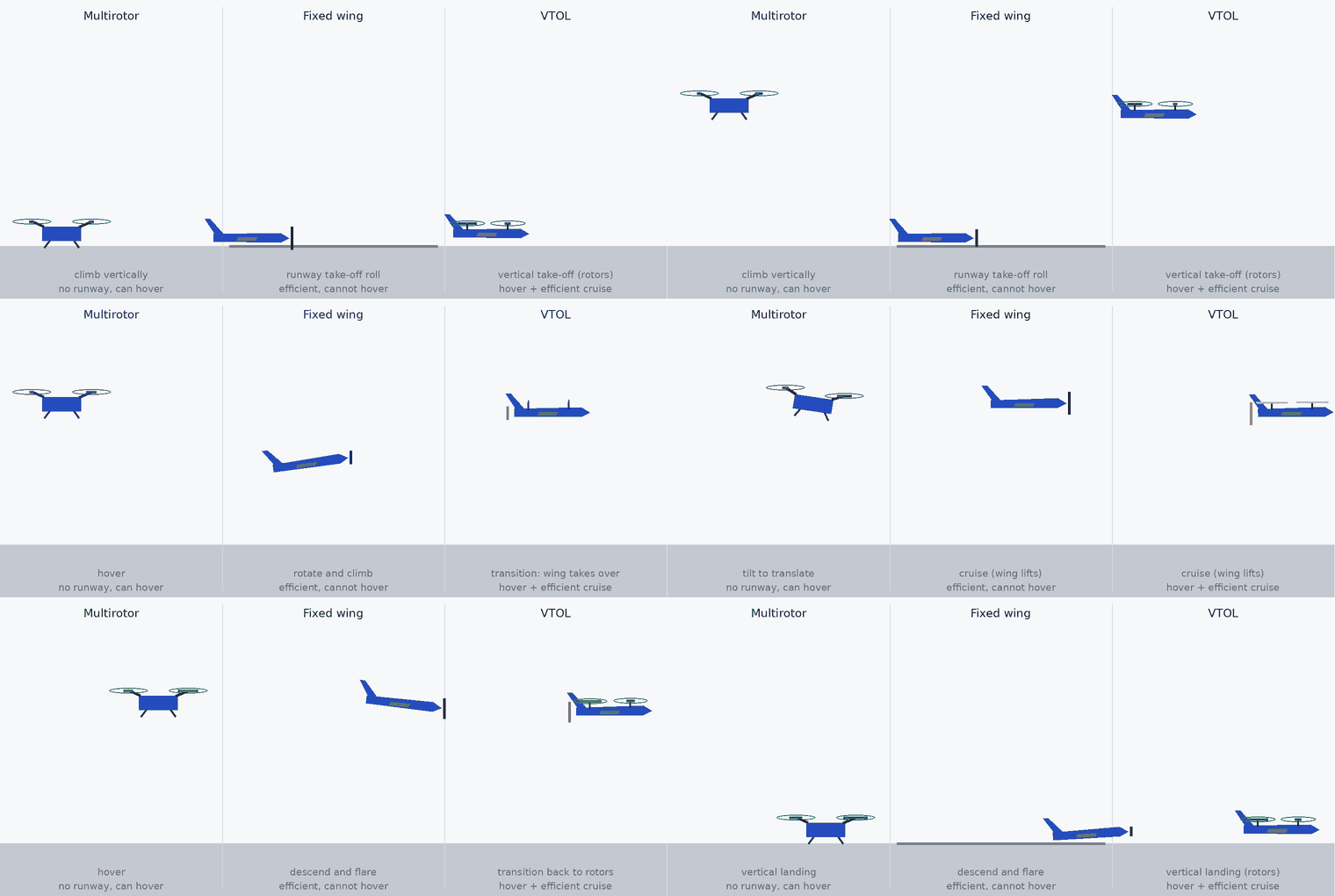
Rotors hover but burn power; wings are efficient but must keep moving; VTOL tries to have both and pays in complexity.
The airframe sets the physics of everything that follows: what the controller must do, how fast the vehicle moves and so how quickly navigation errors grow. This lesson compares the three families with two first-principles power estimates you can check yourself.
Learning objectives
After this lesson, you should be able to:
- Describe how each airframe generates lift and control.
- Estimate hover power (momentum theory) and cruise power (weight over lift-to-drag).
- Compare endurance, hover capability, control complexity and navigation implications.
- Explain why VTOL transition is the hardest part of VTOL design.
Conceptual explanation
A multirotor produces lift with rotors that also provide control: it can hover, take off vertically and fly slowly, at the price of high power. A fixed-wing aircraft produces lift with a wing at forward speed, which is far more efficient but cannot hover and needs a launch and landing method. A VTOL aircraft combines both: hover rotors (and sometimes tilting rotors) for take-off and landing, wing for efficient cruise, with a transition in between.
| Multirotor | Fixed-wing | VTOL (hover rotors + wing) | |
|---|---|---|---|
| Hover | Yes | No | Yes (rotor mode) |
| Cruise efficiency | Low | High | High in cruise, a weight penalty from the lift system |
| Control | Rotor thrust differences | Control surfaces, speed ≥ stall | Both, plus transition logic |
| Navigation challenge | Slow, precise, indoor-capable | Fast: errors grow quickly per second; no stopping | Estimator and controller must handle regime change |
| Failure mode of note | Motor loss: fast attitude loss on quadrotors | Stall | Transition failures |
Engineering intuition
A wing gives lift for the price of drag, which is small (lift-to-drag ratios of ten or more are ordinary), so the power needed to stay aloft is roughly weight × speed divided by /. A rotor holds the vehicle up by throwing air down: the only way to get a given thrust from a small disc is to accelerate a small mass of air a lot, which wastes energy. That is why a big, slow rotor is efficient and a hovering multirotor has endurance measured in tens of minutes while an aeroplane of the same weight can fly for hours.
The navigation consequence is speed: at 20 m/s a 1% odometry drift is 0.2 m per second of flight and a failed sensor cannot be waited out by stopping. Multirotors can hold still to recover; wings cannot.
Mathematical formulation
Hover power from momentum theory (ideal), with thrust , rotor disc area A and air density , as in the endurance calculator:
Level cruise of a fixed wing: lift equals weight, thrust equals drag, so the aerodynamic power is:
- FM
- rotor figure of merit (below 1).
- /
- lift-to-drag ratio at the cruise speed (airframe dependent; measure or take from the manufacturer).
- overall drivetrain efficiency including motor, ESC and propeller.
Wing loading sets the stall speed: for wing area , which is why a fixed-wing cannot fly slowly enough to inspect indoors.
Architecture and data flow
All three share the same autonomy stack shape (sensing → estimation → planning → control), but the control allocation block differs: motor mixing for multirotors (lesson M1-T6), control-surface and throttle allocation for wings, and a blend with a transition state machine for VTOL. PX4 supports all three as airframe types: the estimator (EKF2) is common, and the vehicle-specific controllers differ. Check the PX4 airframe documentation for the supported geometries.
Real-world UAV applications
- Choosing multirotor for indoor and close inspection.
- Choosing fixed-wing or VTOL for corridor mapping over many kilometres.
- Estimating whether a mapping mission is feasible by each airframe before building anything.
- Understanding why fixed-wing GNSS-denied navigation is harder (speed, no hover).
Implementation example
This runs as shown: it compares the electrical power of a 2 kg multirotor in hover with a 2 kg fixed-wing in cruise, under stated assumptions, and the resulting endurance for the same 80 Wh of usable energy.
import numpy as np
g, rho = 9.81, 1.225

def hover_power(mass, rotors, diameter_m, fm=0.6, eta=0.8):
    A = rotors * np.pi * (diameter_m / 2) ** 2; T = mass * g
    return T ** 1.5 / np.sqrt(2 * rho * A) / (fm * eta)

def cruise_power(mass, speed, l_over_d, eta=0.6):
    return mass * g * speed / l_over_d / eta

mass, usable_wh = 2.0, 80.0
p_hover = hover_power(mass, 4, 0.254)                    # 4 rotors, 10-inch propellers
p_wing = cruise_power(mass, 15.0, 10.0)                  # 15 m/s at an assumed L/D of 10
print(f"hover {p_hover:.0f} W -> {usable_wh / p_hover * 60:.0f} min; fixed-wing cruise {p_wing:.0f} W -> {usable_wh / p_wing * 60:.0f} min")
assert p_wing < p_hover and usable_wh / p_wing > 1.5 * usable_wh / p_hover      # the wing is far more efficient under these assumptions
v_stall = np.sqrt(2 * mass * g / (rho * 0.3 * 1.2))                               # 0.3 m^2 wing, CL_max 1.2: illustrative
assert 8 < v_stall < 14Common engineering mistakes
Comparing hover endurance with cruise endurance of other types without stating assumptions
The result depends on /, figure of merit and efficiencies; state them.
Choosing a fixed-wing for a mission that needs hover or very low speed
Stall speed makes indoor and close-range work impractical.
Underestimating VTOL transition risk
Transitions are where VTOL aircraft are most often lost; test them first at altitude.
Assuming the same estimator tuning works across airframes
Dynamics and sensor noise differ.
Ignoring wind
A 20 m/s fixed-wing faces headwinds comparable to its speed on small ones.
Failure modes
| Failure mode | How it shows up | Likely cause |
|---|---|---|
| Stall | Sudden loss of lift and control | Speed below stall speed in a turn or gust (fixed-wing) |
| Motor loss | Quadrotor spins or flips | No redundancy in thrust |
| Failed transition | Loss of control between hover and cruise | Control allocation or airspeed estimate error |
| Short endurance | Cannot finish the mission | Hover chosen where a wing would do |
Debugging approach
- Compute hover and cruise power for your numbers before building.
- Compare predicted and measured power in a bench or flight log.
- For VTOL, log transition state, airspeed and thrust split and inspect them first.
- Check stall margins in the worst turn and gust.
Practical exercises
- Find the cruise speed at which a 2 kg wing with uses the same power as the hovering quadrotor of the example.
- Compute the stall speed of a 2 kg wing with area and .
- Estimate the 1% odometry drift per second of flight at 20 m/s and 2 m/s.
- Name two PX4 airframe types that apply to VTOL and read their configuration pages.
Interview questions
Write an answer in your own words, then reveal the model answer. Nothing is sent anywhere.
Question 1
Why are fixed-wing aircraft so much more efficient than multirotors?
Model answer
A wing lifts for a small drag cost (/ around ten or more), so cruise power is about v/(/), whereas a rotor must accelerate air downward to hover, costing much more power for the same weight.
Question 2
What makes VTOL design hard?
Model answer
The transition between hover and wing-borne flight: control allocation changes, airspeed estimation must be good, and failures there are severe, plus the weight penalty of carrying both systems.
Question 3
How does airframe type affect GNSS-denied navigation?
Model answer
Speed: a fast fixed-wing accumulates position error per second quickly and cannot stop to recover, while a multirotor can hold still.
References and further reading
Primary papers, official documentation and standards. Each claim above that is specific to a tool or version points here.
- . . Leishman, Principles of Helicopter Aerodynamics, 2nd ed., Cambridge University Press, 2006 (momentum theory).
- PX4: airframe reference (multicopter, fixed-wing, VTOL)
- . . Cook, Flight Dynamics Principles, 3rd ed., Butterworth-Heinemann, 2013.