UAV Systems Engineering · Module 1
M1-T3: Quadrotor mechanical and electrical components
Know every part, what it connects to, and what it costs in mass, current and failure risk.
A quadrotor is a small power plant with a computer on top. Most field failures are not algorithmic: they are a loose connector, a sagging battery, a wrong wire gauge or noise on a power rail. This lesson names the parts and traces the two paths that matter, power and signal.
Learning objectives
After this lesson, you should be able to:
- Name the components of a quadrotor and the function of each.
- Trace the power path and compute current, voltage drop and wiring loss.
- Trace the signal paths (control, telemetry, sensors) and the buses used.
- List the integration hazards: vibration, electromagnetic noise, connector failure.
Conceptual explanation
The airframe carries propulsion (propellers, motors, ESCs), energy (battery, power distribution, regulators), avionics (flight controller with IMU, barometer, magnetometer; GNSS receiver; radio and telemetry) and payload (companion computer, cameras, LiDAR, gimbal).
| Component | Function | Typical interface | Common failure |
|---|---|---|---|
| Frame and arms | Carry loads, set stiffness | Mechanical | Cracks, resonance with motor frequency |
| Propeller | Turn rotation into thrust | Motor shaft | Imbalance, chips, wrong direction |
| Motor | Torque from current | Three phases from ESC | Bearing wear, demagnetisation, overheating |
| ESC | Drive the motor | Battery power; PWM/DShot/DroneCAN signal | Desync, overcurrent, noise |
| Battery | Energy | High-current connector | Voltage sag, ageing, damage |
| PDB / regulators | Distribute and regulate power | Battery in; 5 and 12 out | Ripple, overload, brown-out |
| Flight controller | Estimation and control | UART, I², SPI, CAN, USB | Vibration, bad power, wrong parameters |
| Companion computer | Perception, planning | Ethernet, USB, UART | Overheating, power draw spikes |
Engineering intuition
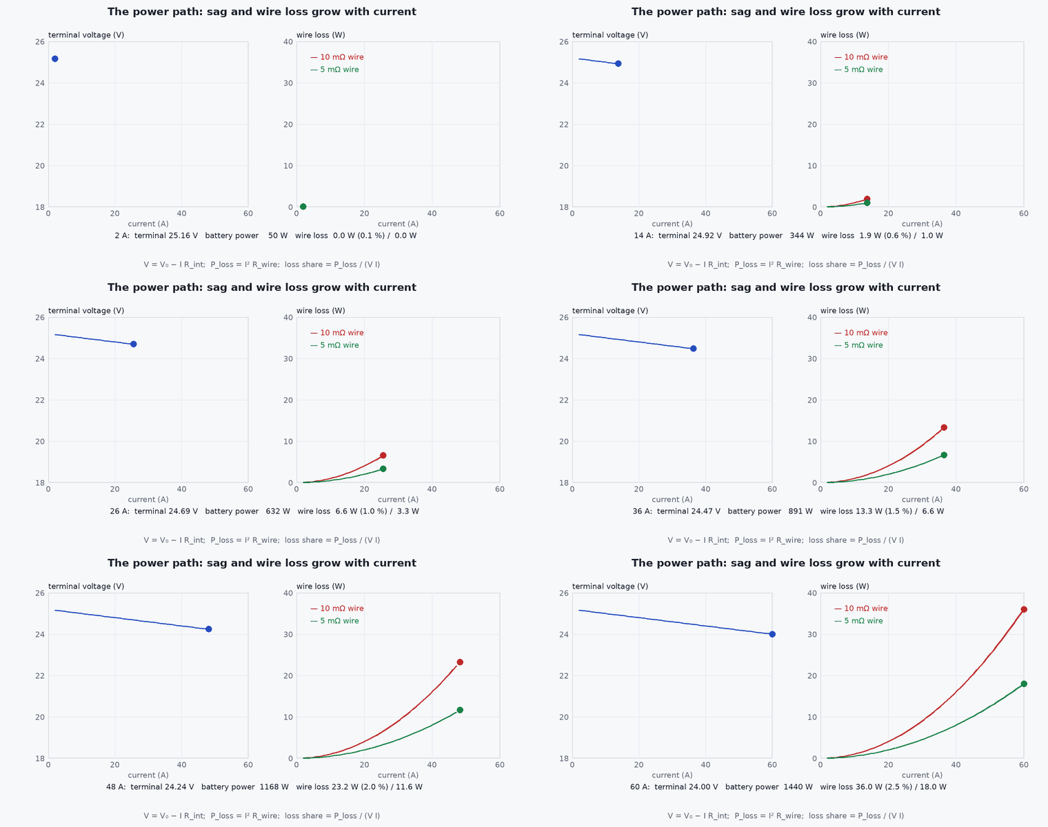
Two numbers explain most integration trouble: current and vibration. A 4S pack feeding 150 of motors draws about 10 A; at full thrust it may draw ten times as much, and every connector, wire and solder joint in that path dissipates . And every propeller spinning slightly out of balance shakes the IMU at its rotation frequency: the vibration enters the estimator as fake acceleration and rapidly poisons attitude, position hold and every VIO that uses that IMU.
The cure for both is design discipline: wire for the peak current with margin, keep high-current paths short and away from sensors, isolate the IMU, and measure.
Mathematical formulation
Current from power and voltage, and the loss in a wire of resistance :
Battery voltage sag under load, with internal resistance and a total pack current I: , which is why a pack that reads 16 at rest can read 13 under a throttle punch and trip a low-voltage brown-out. Motor frequency and its harmonics set the vibration lines to look for in the IMU spectrum: = rpm/60 times the number of blades for blade-pass frequency.
- resistivity of copper.
- ,
- wire length (, out and back) and cross-section .
- battery internal resistance .
- rpm
- rotor speed in revolutions per minute.
Architecture and data flow
Power: battery → connector → PDB → ESC → motor (hundreds of watts, tens of amps) and PDB → regulator → flight controller and companion (watts). Signals: flight controller → ESC (command), ESC → flight controller (telemetry), IMU, baro and mag inside the flight controller, GNSS and radio on UART or CAN, companion ↔ flight controller on UART or Ethernet (lesson M1-T11). Keep noisy switching regulators and ESC wires away from the magnetometer and GNSS antenna.
Real-world UAV applications
- Wiring a new payload without browning out the computer.
- Diagnosing yaw drift caused by a magnetometer near a power wire.
- Specifying the battery and connectors for a 1.5 kg vehicle.
- Deriving the vibration lines to look for in IMU logs.
Implementation example
This runs as shown: current, wiring loss and battery sag for a 4S vehicle at hover and at full throttle.
rho_cu = 1.7e-8

def wire_resistance(length_m, area_mm2): return rho_cu * length_m / (area_mm2 * 1e-6)
def loss_w(current_a, length_m, area_mm2): return current_a ** 2 * wire_resistance(length_m, area_mm2)

v_pack_rest, r_int = 16.0, 0.020                          # 4S pack, 20 milliohm internal resistance (illustrative)
for label, power_w in (("hover", 180.0), ("full throttle", 800.0)):
    i = power_w / v_pack_rest
    for _ in range(20): i = power_w / (v_pack_rest - i * r_int)      # solve for the current with sag included
    sag = i * r_int
    loss = loss_w(i, 0.30, 4.0)                                       # 30 cm out and back of 4 mm^2 copper from battery to PDB
    print(f"{label}: {i:.1f} A, sag {sag:.2f} V, harness loss {loss:.2f} W")
assert abs(wire_resistance(0.3, 4.0) - 1.275e-3) < 1e-6
i_hover = 180 / 16; assert loss_w(i_hover, 0.3, 4.0) < 0.2 and loss_w(50, 0.3, 4.0) > 3.0            # I^2 R grows with the square of current
blade_pass = 7200 / 60 * 2; assert blade_pass == 240.0 # two-blade propeller at 7200 rpm: 240 Hz vibration lineCommon engineering mistakes
Sizing wires for hover current
Peak current is several times higher; wire and connectors must handle it without overheating.
Powering the companion from the same rail as the ESCs without filtering
ESC noise and brown-outs reset the computer.
Hard-mounting the flight controller
Vibration reaches the IMU; use a damped mount and check the vibration levels.
Routing power wires beside the magnetometer
Current-dependent heading error; separate and, if needed, calibrate with motors running.
Ignoring connector ratings
Connectors burn at currents below the wire rating.
Failure modes
| Failure mode | How it shows up | Likely cause |
|---|---|---|
| Brown-out | Reboot on throttle punch | Battery sag or insufficient regulator headroom |
| Heading drift under load | Yaw error grows with throttle | Magnetometer disturbed by wiring currents |
| Vibration-induced estimator failure | Position hold wanders, IMU clipping | Unbalanced propellers, hard-mounted flight controller |
| Overheated connector | Melted plastic, intermittent power | Connector rated below peak current |
Debugging approach
- Measure current and voltage at the battery during a hover and a throttle punch.
- Check the IMU vibration metrics and spectrum with motors running and props on, tethered.
- Thermal-check connectors and ESCs after a hard flight.
- Do a magnetometer-versus-throttle test with props off.
Practical exercises
- Compute the harness loss for 80 A through 0.4 m of wire.
- Estimate the pack voltage sag at 60 A for .
- List the components you would add to a vehicle to carry a LiDAR and a Jetson, with power and mass.
- Find the blade-pass frequency of a three-blade propeller at 6000 rpm.
Interview questions
Write an answer in your own words, then reveal the model answer. Nothing is sent anywhere.
Question 1
Why do electrical problems cause flight problems on a drone?
Model answer
Peak currents cause voltage sag and brown-outs, switching noise couples into sensors and radios, and current-carrying wires disturb the magnetometer; all of these degrade the estimator or reset the computer.
Question 2
How do you check vibration before flying autonomously?
Model answer
Log the IMU, inspect its spectrum and the flight controller’s vibration metrics with props on and motors running, look for clipping and blade-pass lines, and improve balancing and mounting.
Question 3
Why must wires be sized for peak rather than hover current?
Model answer
Peak current occurs in manoeuvres and failsafes, where heating and voltage drop are largest; undersized wires fail exactly when needed.
References and further reading
Primary papers, official documentation and standards. Each claim above that is specific to a tool or version points here.
- PX4: assembly and wiring guides
- PX4: flight controller orientation
- PX4: log analysis (vibration)
- IPC-2221 (generic standard on printed board design) and manufacturer wire and connector ratings for current limits.