UAV Systems Engineering · Module 7
M7-T13: Power and thermal budgets
Every watt the computer draws is a watt less for flying time and a watt of heat to get rid of.
A companion computer costs flight time twice: once in the energy it uses, once in the mass of the battery and cooling to carry it. The heat it makes limits the performance it can sustain. A budget per mode, with ambient temperature as an explicit input, keeps both honest.
Learning objectives
After this lesson, you should be able to:
- Build a per-mode power budget including conversion losses.
- Estimate the effect of avionics power on flight time.
- Compute steady-state temperature for an enclosure given thermal resistance and ambient.
- Define margins and a test that verifies them at the hot case.
Conceptual explanation
Established The relations are basic energy and heat-transfer balance. All numeric values are placeholders for the arithmetic; real budgets need measurements on the real hardware at the real ambient temperature, with the enclosure as flown.
Power budget per mode: list every load (flight controller, companion, sensors, radios, payload, gimbal, lights), its power in each mode, and the conversion efficiency from the battery bus to the rail. Total electrical draw from the battery is . Propulsion usually dominates; avionics power matters most for small vehicles, long-endurance fixed-wing aircraft, and any vehicle that hovers at low thrust.
Thermal budget: nearly all electrical power ends as heat. Inside a closed enclosure on a vehicle with little airflow, the heat leaves by conduction and convection to the airframe and air, characterised by a thermal resistance to ambient. The steady-state internal temperature is , which must remain below each component’s limit (and below the throttle threshold) at the hottest expected ambient, including solar heating of the enclosure.
- Hot case: highest ambient, direct sun, hover (low airflow), full payload; the case that must pass.
- Cold case: batteries lose capacity and voltage under load in the cold; heaters can matter.
- Transients: start-up inrush current, motor-start dips, GPU bursts.
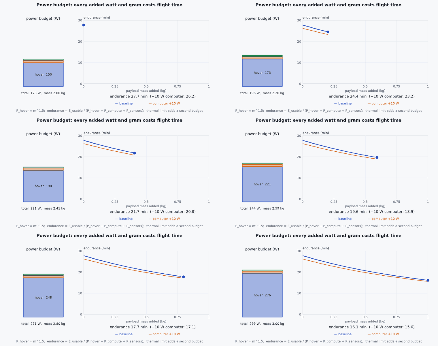
Engineering intuition
Flight time is energy divided by power, so a 20 companion on a vehicle drawing 200 in hover costs about 9 % of the endurance (and more if its mass forces a larger battery). Reducing avionics power by choosing a lower power mode can give back minutes of flight time and also lowers the temperature, which delays throttling: so power modes are a mission-planning variable, not a fixed property.
Heat gets trapped in sealed enclosures on hovering vehicles, where there is no airstream. A box that stays cool on a fixed-wing at 20 m/s may overheat in a 35 °C hover. Test the worst airflow case, not the average one.
Mathematical formulation
Battery energy (Wh, usable fraction of nameplate), total power , flight time
Conversion efficiency: with , 20 at the rail draws 22.2 from the battery, and 2.2 is heat in the regulator. Steady-state temperature and time constant of an enclosure with thermal capacitance :
To keep − margin at requires ≤ (limit − margin − )/. Because depends on airflow, derive and test it at the minimum airflow condition. Battery sag: with internal resistance the terminal voltage under load current I is , so a regulator with a minimum input voltage can brown out under a transient at low state of charge.
- usable fraction of nameplate battery energy.
- conversion efficiency.
- ,
- thermal resistance and capacitance of the enclosure.
- battery internal resistance.
Architecture and data flow
Battery → power distribution board (with current and voltage sensing) → propulsion ESCs and avionics regulators → loads. Measurements: bus voltage and current from the power module (logged by the flight controller), companion power from the module’s own monitor or a shunt, temperatures from on-board sensors and added thermistors. The mission planner uses the power model to predict endurance per mode and the thermal model to decide whether a mode is allowed at the current ambient.
Real-world UAV applications
- Choosing a companion power mode for a long-endurance mission.
- Specifying enclosure ventilation or a heat sink.
- Predicting endurance with and without the payload.
- Defining hot-case and cold-case ground tests.
Implementation example
This runs as shown. A mode-based power and thermal budget with placeholder values: flight time per mode, steady-state and transient temperature at the hot-case ambient, and a pass/fail against limits with margin.
import numpy as np
# PLACEHOLDER numbers for the arithmetic; replace with measurements on your vehicle
battery_wh, usable = 148.0, 0.8
modes = {  # name: (propulsion W, {load: (rail W, efficiency)})
    'hover-inspect': (190.0, {'flight controller': (3.0, 0.9), 'companion': (22.0, 0.9), 'camera+lidar': (12.0, 0.9), 'radio': (4.0, 0.9)}),
    'cruise-map':    (150.0, {'flight controller': (3.0, 0.9), 'companion': (18.0, 0.9), 'camera+lidar': (12.0, 0.9), 'radio': (4.0, 0.9)}),
    'degraded-nav':  (190.0, {'flight controller': (3.0, 0.9), 'companion': (10.0, 0.9), 'camera+lidar': (6.0, 0.9), 'radio': (4.0, 0.9)})}
C_th, T_limit, margin, T_amb_hot = 60.0, 85.0, 10.0, 40.0                      # enclosure heat capacity (J/degC) and limits (illustrative)
def budget(R_th, verbose=True):
    all_ok = True
    for m, (p_prop, loads) in modes.items():
        p_av_bat = sum(w / eta for w, eta in loads.values()); p_heat = p_av_bat                  # all electrical power ends as heat (rails and regulator losses)
        t_min = usable * battery_wh / (p_prop + p_av_bat) * 60
        T_ss = T_amb_hot + R_th * p_heat; ok = T_ss <= T_limit - margin; all_ok &= ok
        if verbose: print(f"R_th {R_th:.1f}: {m:>14}: avionics {p_av_bat:5.1f} W from battery, flight time {t_min:5.1f} min, steady-state T {T_ss:5.1f} C at {T_amb_hot:.0f} C ambient -> {'PASS' if ok else 'FAIL'}")
    return all_ok
ok_vented = budget(0.6); ok_sealed = budget(2.4)                                # a ventilated, heat-sunk enclosure versus a sealed box in hover
t_with = usable * battery_wh / (190 + 45.6) * 60; t_without = usable * battery_wh / 190 * 60
print(f"avionics cost in hover: {t_without - t_with:.1f} min of {t_without:.1f}")
assert ok_vented and not ok_sealed and abs(20 / 0.9 - 22.222) < 1e-3 and t_with < t_without
tau = 0.6 * C_th; T0 = 45.0; T_ss = T_amb_hot + 0.6 * 25.0
print(f"enclosure time constant {tau:.0f} s; temperature after 5 min at 25 W: {T_ss + (T0 - T_ss) * np.exp(-300 / tau):.1f} C (steady state {T_ss:.1f} C)")Common engineering mistakes
Testing thermal performance in a cool lab
The hot, low-airflow, sun-loaded case governs.
Ignoring conversion losses
Rail power is not battery power; regulators dissipate heat too.
Budgeting average power
Peaks and start-up transients set regulator and wire sizing.
Neglecting battery sag and cold
Low voltage under load can brown out the avionics.
No power-mode logic in the mission planner
The same mode can be fine in a cool morning and fail in the afternoon.
Failure modes
| Failure mode | How it shows up | Likely cause |
|---|---|---|
| Thermal shutdown or throttling mid-mission | Perception slows down | Hot case not tested; enclosure sealed |
| Brown-out at low battery | Companion resets near the end of a flight | Battery sag at high current with a regulator minimum input |
| Flight time shorter than planned | Early low-battery landing | Avionics power underestimated, payload added |
| Regulator overheats | Rail collapse | Inadequate heat sinking of converters |
Debugging approach
- Log bus voltage, current and temperatures with the flight log.
- Run a ground test at the hot case with a heat gun or a chamber and measure the steady state.
- Compare predicted and measured endurance and update the model.
- Check start-up inrush with an oscilloscope.
Practical exercises
- Compute the flight-time penalty of a 30 payload on a vehicle drawing 250 in hover.
- Find the maximum that keeps a 28 heat load below 75 °C at 40 °C ambient.
- Plan the hot-case test: conditions, duration, instrumentation, pass criteria.
- Estimate the voltage sag at the regulator input for cell-pack resistance and a 40 A peak (state your battery assumptions).
Interview questions
Write an answer in your own words, then reveal the model answer. Nothing is sent anywhere.
Question 1
How does avionics power affect flight time?
Model answer
It adds to total draw, so the fractional loss in endurance is roughly for fixed propulsion power; extra mass for batteries or cooling adds to propulsion power as well.
Question 2
What is the governing case for a thermal test?
Model answer
The hot case: highest ambient with solar loading, minimal airflow (hover), full payload and the highest-power mode, run long enough to reach steady state.
Question 3
Why can a companion brown out near the end of a flight?
Model answer
The battery’s terminal voltage falls under load as the state of charge drops, and a transient current peak can pull a regulator’s input below its minimum.
References and further reading
Primary papers, official documentation and standards. Each claim above that is specific to a tool or version points here.