UAV Systems Engineering · Module 7
M7-T11: PTP synchronization
PTP can discipline clocks on a vehicle network to far better than software NTP, if the timestamps are taken in hardware and the path is symmetric.
When several sensors and computers on a vehicle have their own clocks, fusing their data needs a common time base. PTP (IEEE 1588) distributes it over Ethernet using timestamps taken as close to the wire as possible. This lesson derives the offset computation and shows what limits its accuracy.
Learning objectives
After this lesson, you should be able to:
- Derive the PTP offset and delay from the four timestamps and state the symmetry assumption.
- Explain why hardware timestamping and PTP-aware switches improve accuracy.
- Compute the offset error from path asymmetry.
- Configure and verify a PTP link with linuxptp tools and read its residual offset.
Conceptual explanation
Established The protocol is specified in IEEE 1588. The accuracy achieved in practice depends on the network interface hardware timestamping support, the switches (boundary or transparent clocks) and temperature stability of the oscillators: it must be measured on the actual vehicle network. No accuracy figure is claimed here.
In PTP a grandmaster clock (often GNSS-disciplined, or the best available oscillator) is distributed through the network. Slaves align themselves to it:
- Offset: how far the slave clock is ahead of the master.
- Path delay: one-way transit time, estimated as half the round trip under the symmetry assumption (forward and backward delays are equal).
- Servo: a controller (usually PI) that adjusts the slave clock’s frequency and phase to drive the offset to zero.
- Hardware timestamping: the network interface or PHY captures timestamps as packets cross the wire, avoiding interrupt and scheduling jitter. Software timestamping works but is far noisier.
- Boundary clocks and transparent clocks: switches that either re-time PTP messages or add their residence time to a correction field, so that switch queueing does not corrupt the delay estimate.
Engineering intuition
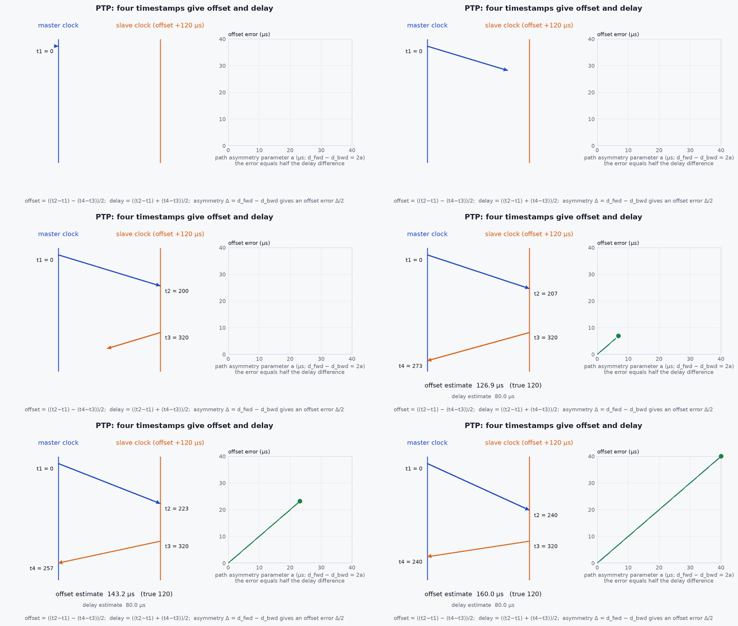
PTP is a careful form of “call, answer, compare watches”. Two messages travel in each direction, each time-stamped at both ends. Subtract the round-trip time from the total to get the offset, assuming the trip each way took the same time. If the forward path takes 10 µs and the return 14 µs, the slave concludes it is 2 µs off when it is not: half the asymmetry becomes offset error. This is why cable and switch choice matter, and why one asymmetric software queue can ruin the sync.
On a UAV the network is small (a few devices on one switch or direct links), which is favourable: few hops, short cables, predictable load. The main practical enemies are software timestamping and bursts of other traffic (video, logs) competing with PTP packets in a non-PTP-aware switch.
Mathematical formulation
Let be the master’s send time of Sync, the slave’s receive time, the slave’s send time of Delay_Req and the master’s receive time. With offset (slave − master) and one-way delays (master to slave) and (slave to master):
The estimate is exact when . In general the offset error is half the asymmetry:
A PI servo with proportional gain and integral gain adjusts the slave frequency correction dt; the integral term absorbs the oscillator’s constant frequency error (tens of ppm for ordinary crystals), and the proportional term removes phase error. Residual jitter is dominated by timestamp noise, oscillator wander between sync messages (a faster sync rate reduces it) and asymmetry.
- slave clock offset relative to the master.
- ,
- one-way path delays in each direction.
- ,
- servo gains.
Architecture and data flow
Grandmaster (GNSS-disciplined or best oscillator) → PTP-capable switch (boundary or transparent clock) → NICs with hardware timestamping on the companion computer, camera, lidar and other devices. On Linux, ptp4l (from linuxptp) runs the protocol and disciplines the NIC’s PTP hardware clock (PHC); phc2sys disciplines the system clock from the PHC. Drivers of sensors that support PTP stamp samples on the PTP clock, and ROS 2 nodes use system time (aligned to PTP by phc2sys) for header stamps. The flight controller’s clock is typically related by a separate mechanism (for example MAVLink timesync), so the end-to-end alignment needs both.
Real-world UAV applications
- Synchronising a lidar, cameras and compute on one vehicle network.
- Multi-vehicle experiments with a common time base.
- Ground-station-to-vehicle timing for latency measurement.
- Providing a common clock for multi-computer logging.
Implementation example
This runs as shown. A simulation of the PTP exchange with a PI servo: a slave with a 40 ppm frequency error, hardware-timestamp noise of 50 ns, a symmetric path and then an asymmetric path. It shows convergence, the residual offset, and the half-asymmetry error.
import numpy as np
rng = np.random.default_rng(11)
def run(asym, T_sync=0.125, T_end=120.0, ts_noise=50e-9, freq_err=40e-6, d_ms=20e-6, kp=0.7, ki=0.3):
    # slave clock = master_time*(1+freq_err) + offset ; a PI servo corrects frequency and phase after each exchange
    theta = 200e-6; corr = 0.0; I = 0.0; est_hist = []; true_hist = []
    t = 0.0
    while t < T_end:
        d_sm = d_ms + asym
        t1 = t; t2 = t1 + d_ms + theta + ts_noise * rng.standard_normal()
        t3 = t2 + 1e-4;  t4 = (t3 - theta) + d_sm + ts_noise * rng.standard_normal()      # master time = slave time - theta
        th_hat = ((t2 - t1) - (t4 - t3)) / 2
        I += ki * th_hat; adj = kp * th_hat + I                                         # PI: phase and frequency correction
        theta -= adj                                                                    # the servo steps the clock by the correction
        theta += (freq_err - 0.0) * T_sync                                              # the oscillator drifts until the next sync
        est_hist.append(th_hat); true_hist.append(theta); t += T_sync
    tail = np.array(true_hist[-200:]); return tail.mean(), tail.std()
m0, s0 = run(0.0); m1, s1 = run(6e-6)
print(f"symmetric: residual mean {m0 * 1e9:7.1f} ns, std {s0 * 1e9:6.1f} ns | asymmetry 6 us: residual mean {m1 * 1e9:8.1f} ns (half of 6 us = 3000 ns)")
assert abs(m0) < 200e-9 and abs(abs(m1) - 3e-6) < 300e-9 and s0 < 500e-9Reference commands for linuxptp on a companion computer (interface names and the master/slave configuration depend on the setup):
ethtool -T eth0                                  # does the NIC support hardware timestamping and a PTP hardware clock?
sudo ptp4l -i eth0 -m -H -s                       # run as a slave (-s) with hardware timestamping (-H), messages to stdout
sudo phc2sys -s eth0 -c CLOCK_REALTIME -w -m # discipline the system clock from the NIC's PHCCommon engineering mistakes
Software timestamping on a loaded network
Jitter of tens to hundreds of microseconds; use hardware timestamping.
Ordinary switches under heavy traffic
Queueing delay varies by direction; use PTP-aware switches or isolate traffic.
Assuming symmetry
Half the asymmetry is the offset error; measure with a loop-back or a pulse reference.
Not syncing the system clock to the PHC
Applications still use an unsynchronised clock; run phc2sys and check it.
Trusting the reported offset
It is the servo’s estimate, not the truth; validate with an independent pulse measurement.
Failure modes
| Failure mode | How it shows up | Likely cause |
|---|---|---|
| Offset oscillates | Servo hunting | Gains too high for the sync rate or noisy timestamps |
| Large constant offset | Stable but wrong | Path asymmetry or a wrong correction field |
| Occasional jumps | Steps of ms | Clock stepping when the system clock and PHC are disputed (NTP and PTP both active) |
| No lock | ptp4l never reaches the slave state | No hardware timestamping support, VLAN or multicast filtering |
Debugging approach
- Read the ptp4l log: offset rms, max, frequency and path delay values.
- Disable NTP/chrony on the interface clock while testing PTP.
- Measure with a hardware reference: compare a PPS output from each device on an oscilloscope.
- Check ethtool -T for hardware timestamping on every device.
Practical exercises
- Compute the offset error for a 3 µs forward and 9 µs return delay.
- Run the simulation with a 1 s sync interval and report the residual std; explain the change.
- Measure the offset between two Linux hosts with ptp4l and record the rms over ten minutes.
- List which devices on your vehicle support PTP and which need another method.
Interview questions
Write an answer in your own words, then reveal the model answer. Nothing is sent anywhere.
Question 1
How does PTP compute the clock offset?
Model answer
From four timestamps (Sync send and receive, Delay_Req send and receive): offset is half the difference of the two one-way measured times, assuming a symmetric path; the mean delay is half their sum.
Question 2
Why does path asymmetry limit PTP accuracy?
Model answer
The algorithm attributes half of any difference between forward and backward delay to the clock offset, so an asymmetry of a microsecond causes half a microsecond of error that no amount of averaging removes.
Question 3
Why use hardware timestamping?
Model answer
Timestamps taken in the NIC or PHY avoid interrupt and scheduling jitter in software, which otherwise dominates the error budget.
References and further reading
Primary papers, official documentation and standards. Each claim above that is specific to a tool or version points here.