UAV Systems Engineering · Module 6
M6-T12: QGroundControl
QGroundControl is more than a map: it is the calibration tool, the parameter editor, the mission planner and the MAVLink inspector.
Most of the bench and field work on a PX4 vehicle happens in QGroundControl: sensor calibration, safety configuration, parameter review, mission upload and live monitoring. Using it deliberately (with a checklist and a saved record) is what separates a repeatable test from an anecdote.
Learning objectives
After this lesson, you should be able to:
- Connect QGroundControl to a simulated and a real vehicle and read its status.
- Calibrate sensors and configure safety settings, and know what each calibration changes.
- Manage parameters: export, compare and restore.
- Use the MAVLink inspector, analyze tools and logs for engineering diagnosis.
Conceptual explanation
Implementation-specific QGroundControl is the reference ground station for PX4 and also works with ArduPilot. Its menus and views change between releases; the workflow here is stable but the labels may differ. Follow the user guide for your version.
QGroundControl (QGC) is a cross-platform ground control station. The views you will use most:
- Vehicle setup: firmware, airframe, sensor calibration (gyro, accelerometer, magnetometer), radio, flight modes, power and safety (failsafes, geofence, return settings).
- Parameters: view, search and edit every autopilot parameter; export the whole set to a file and compare against a baseline.
- Plan: create waypoint missions, set altitude and speed per item, upload and download them.
- Fly: live map, telemetry, mode switching and commands.
- Analyze tools: the MAVLink Inspector (live message rates and fields), MAVLink console (a shell onto the autopilot), log download and the vibration view.
Engineering intuition
Use QGC like a lab instrument. Before every flight, note the firmware version, load the parameter file, and compare it with the baseline. After every flight, download the log and write down what happened. If something odd occurs in the air, the MAVLink Inspector and the console let you check, in seconds, whether the vehicle believes what you believe: the estimator status, the sensors and the failsafe flags.
The calibrations deserve respect. A gyro or accelerometer calibration depends on the vehicle being still and level; a compass calibration depends on the environment being free of magnetic disturbance. A bad calibration looks like a controller or estimator bug in the air.
Mathematical formulation
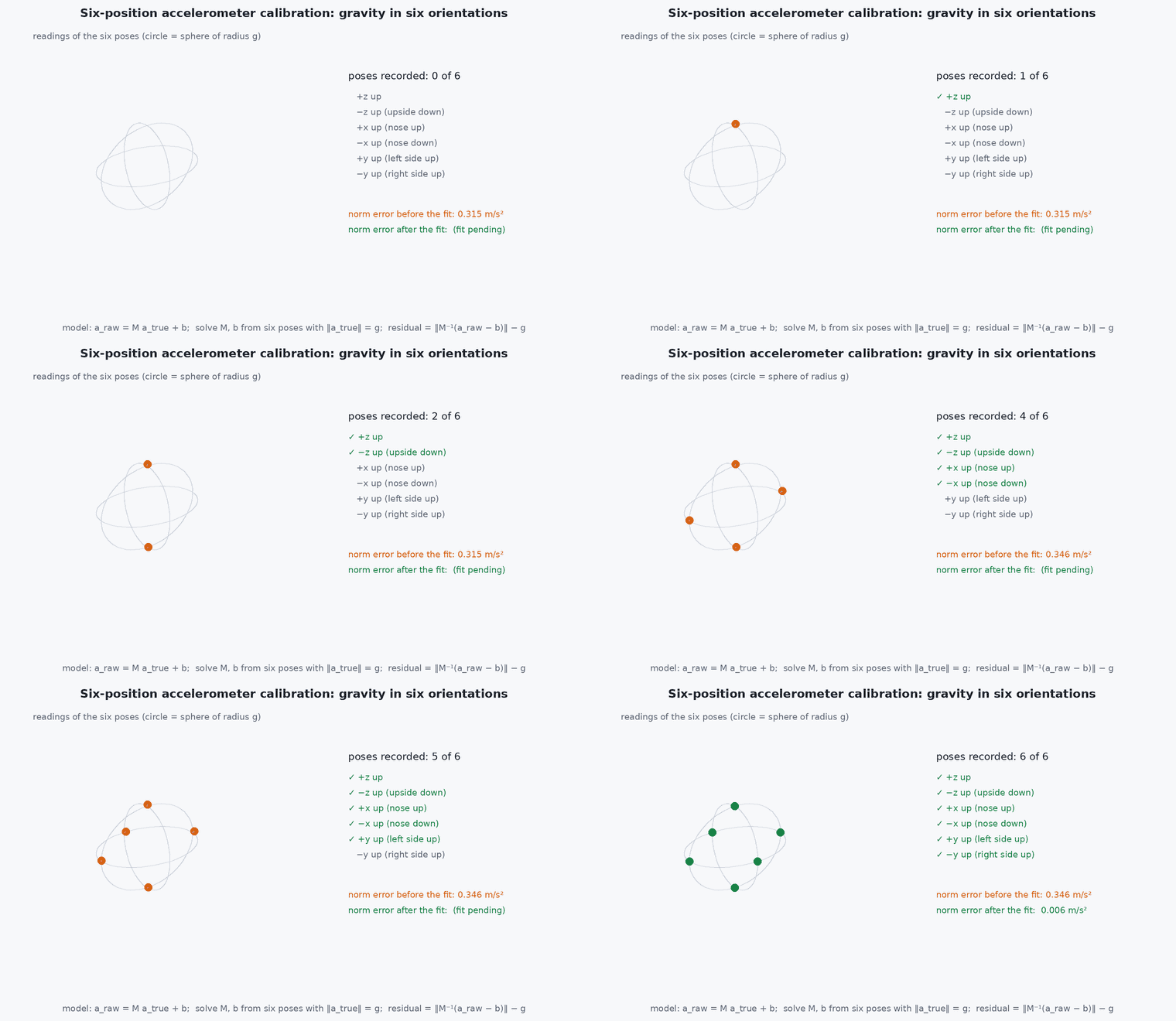
Calibration fits a model to raw readings. For an accelerometer, the sensor output relates to the true specific force by scale factors, axis misalignment and bias: . The six-position calibration collects stationary readings in six orientations (±, ±, ± up), where is known, and solves for and :
Magnetometer calibration fits an ellipsoid (hard-iron offset and soft-iron distortion) to readings taken while rotating through all orientations, mapping them to a sphere of radius equal to the local field magnitude. The quality of both depends on pose diversity: a calibration with poses in only one plane leaves the other axes unconstrained. A useful check after calibrating is the residual: the spread of across poses, which should be small compared with .
- ,
- accelerometer scale/misalignment matrix and bias.
- gravity magnitude .
Architecture and data flow
QGC ↔ MAVLink (UDP from SITL or a telemetry radio, or a USB serial) ↔ PX4 MAVLink module ↔ uORB. Parameter reads and writes use the MAVLink parameter protocol; missions use the mission protocol; calibration commands are MAVLink commands with status messages back. The log download uses the MAVLink log-transfer messages. If several ground stations or a companion computer share the link, a MAVLink router distributes streams.
Real-world UAV applications
- Bench setup and calibration of a new airframe.
- Pre-flight checks and parameter baselines for test campaigns.
- Mission planning for repeatable autonomy tests.
- Live diagnosis during SITL and flight tests with the MAVLink Inspector and console.
Implementation example
This runs as shown. A six-position accelerometer calibration on synthetic data: raw readings with scale, misalignment and bias, solved by least squares, with the residual check.
import numpy as np
rng = np.random.default_rng(2)
g = 9.81
M_true = np.array([[1.02, 0.01, -0.005], [0.0, 0.98, 0.012], [0.003, -0.002, 1.01]]); b_true = np.array([0.15, -0.08, 0.22])
poses = np.array([[0, 0, 1], [0, 0, -1], [1, 0, 0], [-1, 0, 0], [0, 1, 0], [0, -1, 0]]) * g
raw = (M_true @ poses.T).T + b_true + 0.01 * rng.standard_normal(poses.shape)       # raw readings in the six static poses

# solve  raw = a_true M^T + b  for M and b by linear least squares (known true specific force in each pose)
X = np.hstack([poses, np.ones((6, 1))]); sol, *_ = np.linalg.lstsq(X, raw, rcond=None)
M_est, b_est = sol[:3].T, sol[3]
corr = np.linalg.solve(M_est, (raw - b_est).T).T
resid = np.linalg.norm(corr, axis=1) - g
print("bias error (m/s^2):", np.round(b_est - b_true, 3), " max |norm - g| after calibration: %.3f" % np.abs(resid).max())
assert np.allclose(b_est, b_true, atol=0.03) and np.abs(resid).max() < 0.05
print("uncalibrated max |norm - g|: %.3f" % np.abs(np.linalg.norm(raw, axis=1) - g).max())A pre-flight checklist to keep with the vehicle:
[ ] firmware version and hash recorded
[ ] parameter file diffed against baseline (no unexplained changes)
[ ] sensors calibrated this session or within the validity period; no calibration warnings
[ ] GNSS fix / vision odometry valid; EKF status OK; home position set
[ ] failsafe actions checked (link loss, RC loss, battery, estimator)
[ ] geofence and return altitude set for this site
[ ] mission uploaded and read back; first waypoint reasonable
[ ] logging enabled, card present; battery fully charged and voltage OK
[ ] pilot in the loop, kill switch tested, safety observer briefedCommon engineering mistakes
Calibrating near metal or live wires
The compass calibration absorbs the disturbance and fails in flight.
Changing parameters without saving the old set
No way to know what changed; export before editing.
Not reading back the uploaded mission
Confirm the vehicle holds what you planned.
Ignoring calibration warnings
They are early signs of sensor problems.
Using a different QGC version without checking
Menus and defaults change; record the version.
Failure modes
| Failure mode | How it shows up | Likely cause |
|---|---|---|
| Calibration fails repeatedly | Error after the last pose | Magnetic disturbance, poor poses, damaged sensor |
| Parameters not saved | Changes lost after reboot | Write failed or reboot required |
| No connection | QGC does not see the vehicle | Wrong port, baud rate, firewall or link configuration |
| Mission rejected | Upload error | Invalid item, missing home, frame mismatch |
Debugging approach
- Use the MAVLink Inspector to confirm the vehicle is streaming and at what rate.
- Use the MAVLink console to read sensor and estimator status.
- Export the parameter set and diff it with the baseline.
- Download the log immediately after the flight and look at vibration and estimator status.
Practical exercises
- Connect QGC to PX4 SITL and list the first ten parameters and their values.
- Export the parameter set, change two parameters, export again and diff them.
- Plan a square mission, upload it and read it back.
- Use the MAVLink Inspector to measure the rate of the attitude and heartbeat messages.
Interview questions
Write an answer in your own words, then reveal the model answer. Nothing is sent anywhere.
Question 1
Why diff parameter sets before and after a test?
Model answer
Undocumented parameter changes make results irreproducible and can hide the cause of a failure; a diff against a baseline documents exactly what differs.
Question 2
What does the accelerometer calibration estimate?
Model answer
Bias, scale factor and axis misalignment, using static poses with known gravity; the residual of the norm against after calibration checks quality.
Question 3
What would you check first if the vehicle flies badly right after calibration?
Model answer
The calibration quality and warnings, the sensor values (norm of acceleration at rest, heading against a reference), and the estimator status in the log.
References and further reading
Primary papers, official documentation and standards. Each claim above that is specific to a tool or version points here.