UAV Systems Engineering · Module 1
M1-T4: UAV coordinate frames: Body, World, NED and ENU
Four letters decide whether a UAV flies where you told it to: get NED, ENU, FRD and FLU straight before touching any code.
Every sensor reading, setpoint and estimate is a vector expressed in some frame. A wrong frame does not cause an error message; it causes a vehicle that flies away from where it was told to go. This lesson fixes the frames used in UAV software and the exact conversions between them.
Learning objectives
After this lesson, you should be able to:
- Define the body, world, NED and ENU frames and the handedness of each.
- Convert positions, velocities and yaw between NED and ENU, and body vectors between FRD and FLU.
- Rotate a body-frame vector into the world frame with a ZYX Euler rotation matrix.
- Name the frame conventions used by PX4 and by ROS 2 and find the conversion needed at the boundary.
Conceptual explanation
A frame is an origin and three orthogonal axes. UAV systems use two families. World (navigation) frames are fixed to the Earth near the vehicle and are used for position, velocity and waypoints. Body frames are fixed to the airframe, with the origin at the centre of mass, and are used for IMU data, thrust direction and angular rates.
NED (North-East-Down) is the aerospace convention and the one used by PX4 for position and velocity. ENU (East-North-Up) is the convention of the Robot Operating System: REP-103 specifies ENU for world frames and FLU (forward-left-up) for body frames. All four frames are right-handed, so in each.
| Frame | Used by | |||
|---|---|---|---|---|
| NED | North | East | Down | PX4 and aerospace: position, velocity |
| ENU | East | North | Up | ROS world frames (map, odom) |
| FRD | Forward | Right | Down | PX4 body frame |
| FLU | Forward | Left | Up | ROS body frame (base_link) |
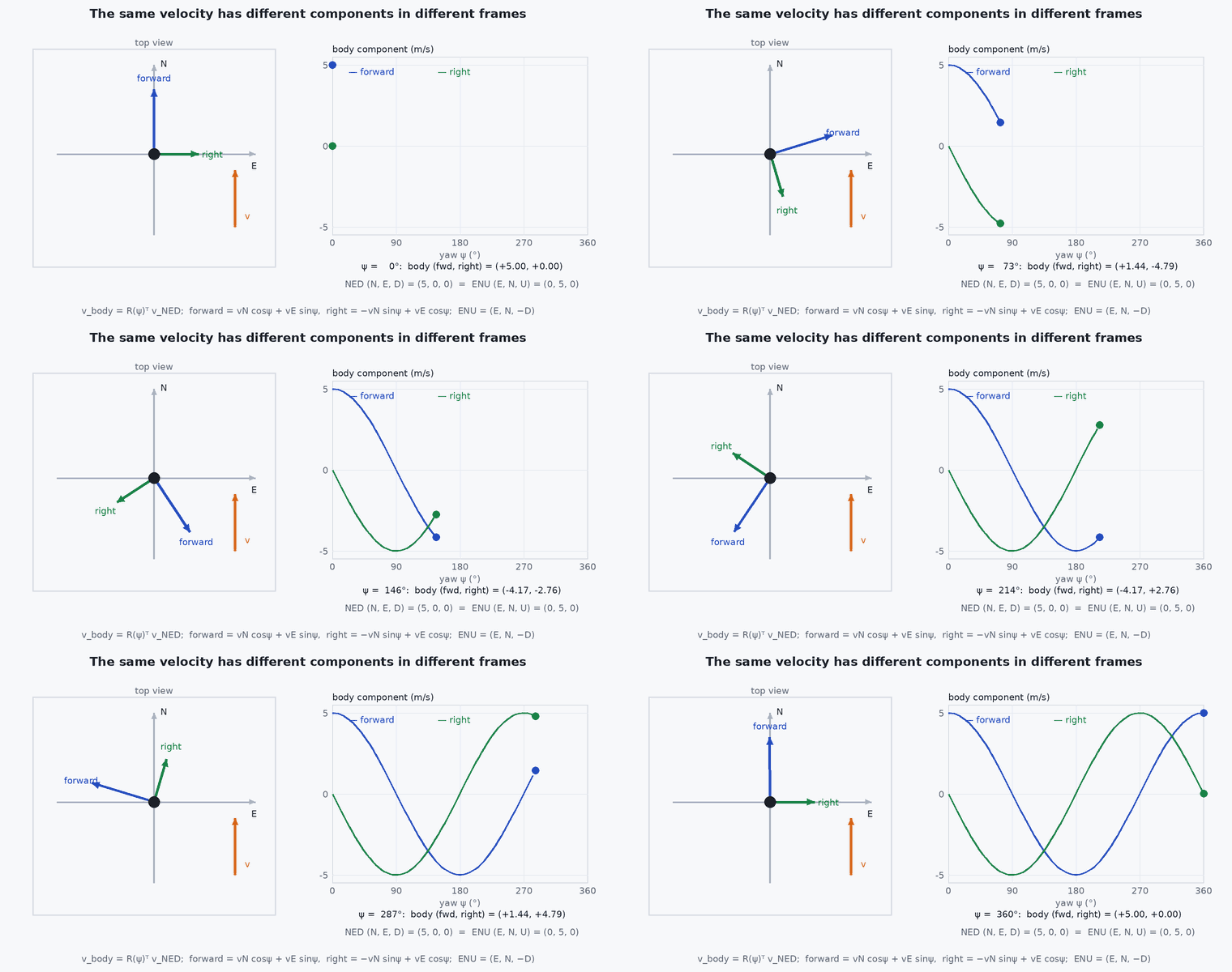
Engineering intuition
Altitude is the quickest sanity check. In NED a vehicle 10 m above the ground has . In ENU the same vehicle has . If a takeoff sends the UAV into the ground, suspect a missing sign flip on before anything else.
The conversions are index shuffles with a sign flip, so they are cheap and exact. Keep every variable name tagged with its frame (p_ned, v_enu, acc_flu) and convert at one place, the boundary between systems. A conversion hidden in the middle of an algorithm is where the bug will be.
Yaw is the second trap. NED yaw is measured clockwise from north (a compass heading). ENU yaw is measured counter-clockwise from east (the usual maths angle). They are related by : a UAV facing east has NED yaw and ENU yaw .
Mathematical formulation
Position and velocity
As a matrix, with the rotation that expresses an NED vector in ENU coordinates:
Its determinant is +1 (swapping two axes contributes a factor −1 and flipping another −1), so it is a proper rotation: a rotation of about the axis , for which nn. The conversion is exact and loses no information.
Body vectors
Body to world with Euler angles
With yaw (about the down or up axis), pitch and roll applied in the ZYX order, a body vector is rotated into the world frame by :
- , ,
- roll, pitch, yaw (rad) about the body , , axes (applied yaw first, then pitch, then roll).
- ,
- cos and sin of the angle that follows.
- rotation matrix: orthogonal, with and .
In NED/FRD with the angles defined as in PX4 (roll positive right-wing-down, pitch positive nose-up, yaw clockwise from north) this is the matrix that maps body FRD vectors into NED. Hovering at level attitude, the thrust vector in FRD is (0, 0, −): thrust points up, which is negative in a down-positive frame.
Euler angles have a singularity at pitch = ± (gimbal lock). Autopilots store attitude as a quaternion (lesson M5-T4) and use Euler angles only for display.
Architecture and data flow
Frame conversions live at interface boundaries. In the usual PX4 plus ROS 2 stack the data cross them as shown:
- IMU on the flight controller: body FRD, consumed by EKF2 inside PX4.
- EKF2 output to the companion over uXRCE-DDS: NED position and velocity, FRD body rates, quaternion from FRD to NED (
px4_msgs/VehicleOdometry). - Companion algorithms (VIO, planners) in ROS: ENU world, FLU body.
- Setpoints back to PX4 over uXRCE-DDS: NED. Odometry from the companion to EKF2: converted from ENU/FLU to NED/FRD.
The conversion code therefore appears exactly twice in a well-structured system: once going from PX4 to ROS and once coming back. The px4_ros_com package provides frame-transform helpers for this purpose.
Real-world UAV applications
- Feeding visual-inertial odometry (computed in ROS ENU/FLU) into PX4’s EKF2 (NED/FRD) as external vision.
- Sending a position setpoint “5 m north of home at 10 m altitude” in offboard mode: (5, 0, −10) in NED.
- Interpreting an IMU log: gravity measured by a level, stationary FRD accelerometer is (0, 0, −), because the sensor measures specific force (reaction to gravity), not gravity.
- Combining LiDAR points (sensor frame) with attitude (body frame) and position (world frame) into a map.
Implementation example
A small, tested conversion module is the first thing to write in any UAV autonomy stack. This runs as shown; the round-trip checks catch a wrong sign immediately.
import numpy as np

def ned_to_enu(p):          # (N, E, D) -> (E, N, U)
    return np.array([p[1], p[0], -p[2]])

def enu_to_ned(p):          # (E, N, U) -> (N, E, D)
    return np.array([p[1], p[0], -p[2]])

def frd_to_flu(v):          # (x, y, z) body: forward, right, down -> forward, left, up
    return np.array([v[0], -v[1], -v[2]])

def yaw_ned_to_enu(psi):    # compass heading (cw from north) -> angle ccw from east
    return (np.pi / 2 - psi + np.pi) % (2 * np.pi) - np.pi

def rot_zyx(roll, pitch, yaw):
    cr, sr, cp, sp, cy, sy = np.cos(roll), np.sin(roll), np.cos(pitch), np.sin(pitch), np.cos(yaw), np.sin(yaw)
    return np.array([[cy*cp, cy*sp*sr - sy*cr, cy*sp*cr + sy*sr],
                     [sy*cp, sy*sp*sr + cy*cr, sy*sp*cr - cy*sr],
                     [-sp,   cp*sr,            cp*cr]])

# 1. round trips are exact
p = np.array([3.0, -2.0, -10.0])                 # 10 m above ground in NED
assert np.allclose(enu_to_ned(ned_to_enu(p)), p)
assert ned_to_enu(p)[2] == 10.0                  # up is positive in ENU

# 2. facing east: NED yaw 90 deg == ENU yaw 0
assert abs(yaw_ned_to_enu(np.pi / 2)) < 1e-12

# 3. a level vehicle facing east: body forward axis points east
fwd_ned = rot_zyx(0.0, 0.0, np.pi / 2) @ np.array([1.0, 0.0, 0.0])
assert np.allclose(fwd_ned, [0.0, 1.0, 0.0])     # (N, E, D) = (0, 1, 0)

# 4. R is a proper rotation
R = rot_zyx(0.2, -0.3, 1.0)
assert np.allclose(R @ R.T, np.eye(3)) and abs(np.linalg.det(R) - 1) < 1e-12
print("all frame checks pass")Common engineering mistakes
Forgetting the sign flip on z
The vehicle “climbs” into the ground or the altitude controller pushes the wrong way. Always check the sign of against “10 m above ground”.
Converting position but not yaw
A vehicle that translates correctly but points off. Yaw conventions differ, not only axes.
Treating Euler angles as vectors
Roll, pitch and yaw do not add or convert like vectors. Convert the quaternion or rotation matrix, then extract angles if needed.
Confusing the rotation of a vector with the rotation of a frame
rotates body coordinates into world coordinates; its transpose does the reverse. Name matrices by direction (R_world_from_body).
Doing conversions inside algorithms
Two different parts of the system then silently assume different frames. Convert at the interface only.
Failure modes
| Failure mode | How it shows up | Likely cause |
|---|---|---|
| Altitude sign error | Vehicle drives into the ground after takeoff or diverges vertically | Down vs up mismatch between estimate and setpoint |
| Swapped and | Vehicle flies east when told north | ENU vs NED axis order not converted |
| Yaw offset of or | Correct shape of path but rotated; camera-IMU extrinsics seem “wrong” | Compass heading used as east-referenced angle, or the reverse |
| Mirror-image trajectory | Path is flipped left to right | Left-handed frame created by flipping one axis without flipping another |
Debugging approach
- Command a known motion (for example 2 m north, then 2 m up) and print the setpoint, the estimate and the logged result in one frame.
- Hold the vehicle by hand, tilt it nose-down and check the sign of pitch and of the accelerometer’s component in both frames.
- Round-trip every conversion in a unit test and assert the sign of gravity and of altitude.
- Plot against of the estimate and of an independent reference (GNSS or motion capture) on one chart; a rotation, flip or swap is obvious.
Practical exercises
- Convert the NED position (120, −45, −30) to ENU and state in words where the vehicle is.
- A vehicle faces south-west. Give its yaw in NED and in ENU.
- Show that is a proper rotation by computing its determinant, and find its rotation axis and angle.
- A level, stationary FRD accelerometer reads (0, 0, −9.81). Predict the reading in FLU, and after a nose-up pitch.
- Write a unit test that fails if anyone changes the sign convention of one conversion.
Interview questions
Write an answer in your own words, then reveal the model answer. Nothing is sent anywhere.
Question 1
What is the difference between NED and ENU, and which do PX4 and ROS use?
Model answer
NED is North-East-Down and ENU is East-North-Up. PX4 uses NED for world frames and FRD for the body; ROS (REP-103) uses ENU for world frames and FLU for the body. Position converts as .
Question 2
A UAV flies correctly in a straight line in SITL but mirrored on a real VIO input. What do you check first?
Model answer
The frame conventions at the VIO-to-EKF2 boundary: ENU/FLU versus NED/FRD, including the sign of and and the yaw convention, and whether a single axis flip produced a left-handed frame.
Question 3
Why does a stationary level accelerometer read +g up (or − in a down-positive frame) rather than zero?
Model answer
An accelerometer measures specific force: the non-gravitational force per unit mass. Resting on a surface, the support force equals − in the inertial sense, so it reads 1 opposite to gravity, which points up in a z-up frame and is − on in a z-down frame.
References and further reading
Primary papers, official documentation and standards. Each claim above that is specific to a tool or version points here.
- REP 103: Standard units of measure and coordinate conventions (ROS)
- PX4 ROS 2 user guide: frame conventions and px4_ros_com
- R. Mahony, V. Kumar, P. Corke, “Multirotor aerial vehicles”, IEEE RAM, 2012 (modelling and frame conventions)
- . . Groves, Principles of GNSS, Inertial, and Multisensor Integrated Navigation Systems, 2nd ed., Artech House, 2013 (frames and rotations).