UAV Systems Engineering · Module 7
M7-T15: Sensor calibration
Every algorithm downstream trusts the calibration. Make it measurable, verifiable and re-doable.
Visual odometry, mapping and fusion all assume that pixel coordinates map to rays by a known model. Intrinsic calibration estimates that model. It is a measurement like any other: it has an error, a validity range and a way to be checked, and it should be repeated when its conditions change.
Learning objectives
After this lesson, you should be able to:
- Write the pinhole-plus-radial-distortion model and identify its parameters.
- Run a calibration with enough pose diversity and evaluate the reprojection error on held-out data.
- Interpret the reprojection error and its relation to a parameter’s uncertainty.
- Define triggers for recalibration (shock, temperature, lens change) and record calibration metadata.
Conceptual explanation
Established Camera calibration from planar targets follows Zhang (2000); the radial-tangential distortion model is standard. The right distortion model (radial-tangential, equidistant fisheye, others) depends on the lens, and the achievable reprojection error depends on the camera, the target and the procedure: no number is claimed here.
The pinhole model maps a 3D point (, , ) in the camera frame to normalised coordinates , applies a distortion, and then the intrinsic matrix:
- Intrinsics: focal lengths , (in pixels) and principal point , sometimes skew.
- Distortion: radial terms , , and tangential , for the usual model; fisheye lenses use a different model.
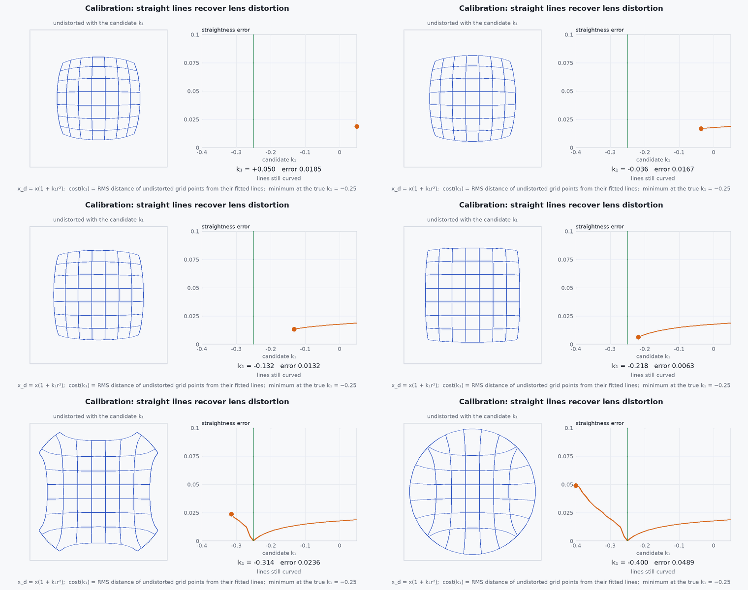
- Calibration: minimise the reprojection error over the parameters and the target poses, using images of a known target (a checkerboard or an AprilGrid) in many orientations and distances, with the target covering the image corners.
Engineering intuition
The calibration is only as good as the data diversity. Images with the target flat-on and centred leave the focal length and the distortion unconstrained; tilted views at several distances, covering the whole image including corners, constrain them. A low reprojection error on the images used for fitting is easy to get with too many parameters; a low error on held-out images is the evidence.
Calibrations drift: a lens barrel that rotates, thermal expansion, a bump, a refocus. The principal point and the distortion are especially sensitive. Treat the calibration file as having a lifetime: store the temperature, date, focus setting and software version with it, and re-check with a quick target test before critical flights.
Mathematical formulation
With camera-frame point (, , ), normalised , , radial distortion and the intrinsic map:
The calibration minimises the sum of squared reprojection residuals over all target points in all images :
The RMS reprojection error is √(cost / (2 N)), with points; it is an estimate of the pixel noise if the model is right. A value several times the corner-detection noise indicates a wrong model or poor data; a value below the noise on training data with large held-out error indicates overfitting. The parameter covariance from the Gauss-Newton Hessian, , gives the uncertainty of each parameter; the uncertainty of typically falls roughly as and improves with view diversity. Projected errors matter more than parameters: a 1 % focal length error at the image edge ( ≈ 0.5 normalised) shifts a point by about 0.01 × 0.5 × pixels, e.g. 3 px for px.
- intrinsic matrix with , , , .
- ,
- radial distortion coefficients.
- pixel noise of corner detection.
Architecture and data flow
Capture tool → image set (stored with exposure, focus, temperature) → corner detector → calibration solver (OpenCV, Kalibr, Basalt or similar) → camera info file (, distortion, resolution, model name, reprojection error, date, hardware serial) → driver publishes camera_info → undistortion or the VIO front end’s camera model. The calibration file is part of the configuration baseline (see the configuration management lesson).
Real-world UAV applications
- Preparing cameras for VIO and mapping.
- Checking calibration after a crash or a lens change.
- Comparing calibrations across a fleet.
- Choosing a distortion model for a wide-angle lens.
Implementation example
This runs as shown. A didactic calibration of focal lengths, principal point and from synthetic corner detections of a planar board in 12 poses. To keep it short the board poses are given (a real calibration estimates them too, for example by homographies as in Zhang’s method). It reports training and held-out reprojection error, and shows what a wrong costs.
import numpy as np
rng = np.random.default_rng(13)
K_true = dict(fx=612.0, fy=608.0, cx=322.0, cy=241.0, k1=-0.28)
def project(P, K):
    x, y = P[:, 0] / P[:, 2], P[:, 1] / P[:, 2]; r2 = x * x + y * y; s = 1 + K['k1'] * r2
    return np.stack([K['fx'] * x * s + K['cx'], K['fy'] * y * s + K['cy']], axis=1)
grid = np.array([[i * 0.04, j * 0.04, 0.0] for i in range(-4, 5) for j in range(-3, 4)])        # 9 x 7 board, 4 cm squares
def pose(rx, ry, rz, t):
    cx, sx, cy, sy, cz, sz = np.cos(rx), np.sin(rx), np.cos(ry), np.sin(ry), np.cos(rz), np.sin(rz)
    R = np.array([[cz, -sz, 0], [sz, cz, 0], [0, 0, 1]]) @ np.array([[cy, 0, sy], [0, 1, 0], [-sy, 0, cy]]) @ np.array([[1, 0, 0], [0, cx, -sx], [0, sx, cx]])
    return R, np.array(t)
def make_set(n):
    out = []
    for _ in range(n):
        R, t = pose(rng.uniform(-0.6, 0.6), rng.uniform(-0.6, 0.6), rng.uniform(-0.3, 0.3), [rng.uniform(-0.15, 0.15), rng.uniform(-0.1, 0.1), rng.uniform(0.35, 0.7)])
        P = grid @ R.T + t; out.append((P, project(P, K_true) + 0.3 * rng.standard_normal((len(P), 2))))      # 0.3 px corner noise
    return out
train, test = make_set(12), make_set(6)
names = ['fx', 'fy', 'cx', 'cy', 'k1']
def resid(theta, data):
    K = dict(zip(names, theta)); return np.concatenate([(project(P, K) - z).ravel() for P, z in data])
def gauss_newton(theta, data, iters=15):
    for _ in range(iters):
        r = resid(theta, data); J = np.empty((r.size, len(theta)))
        for i in range(len(theta)):
            e = np.zeros(len(theta)); e[i] = 1e-6 * max(1.0, abs(theta[i])); J[:, i] = (resid(theta + e, data) - r) / e[i]
        theta = theta - np.linalg.lstsq(J, r, rcond=None)[0]
    return theta, J
rms = lambda theta, data: float(np.sqrt(np.mean(resid(theta, data) ** 2)))
theta0 = np.array([500.0, 500.0, 320.0, 240.0, 0.0])                                         # a rough initial guess
theta, J = gauss_newton(theta0, train)
sd = rms(theta, train) * np.sqrt(np.diag(np.linalg.inv(J.T @ J)))
print("estimated:", dict(zip(names, np.round(theta, 3))), "  std:", np.round(sd, 3))
print(f"RMS reprojection error: train {rms(theta, train):.3f} px, held-out {rms(theta, test):.3f} px")
wrong = theta.copy(); wrong[4] = 0.0
print(f"with k1 forced to 0 (distortion ignored): held-out {rms(wrong, test):.2f} px")
assert rms(theta, test) < 0.5 and abs(theta[0] - 612.0) < 5 and abs(theta[4] + 0.28) < 0.02 and rms(wrong, test) > 3 * rms(theta, test)With OpenCV the corresponding call is cv2.calibrateCamera on detected corners (it also estimates the poses); keep a held-out set and report both errors.
Common engineering mistakes
Training error only
Report held-out error; a model can fit its own data and still be wrong.
Target always flat-on and centred
Focal length and distortion are unconstrained; tilt the board and cover the corners.
Calibrating at a different focus or resolution
Intrinsics change with focus and cropping; calibrate in the configuration you fly.
Too many distortion terms
Extra coefficients overfit on few images; start with k1, k2.
Not recording the conditions
A calibration with no date, temperature and hardware serial cannot be audited.
Failure modes
| Failure mode | How it shows up | Likely cause |
|---|---|---|
| VIO scale or tracking error | Drift from a wrong focal length or principal point | Calibration error or a model mismatch at image edges |
| Straight lines look curved after undistortion | Residual distortion | Wrong model for the lens or too few coverage images |
| Calibration worsens after a crash | Larger reprojection error | Lens or sensor shifted mechanically |
| Drift over temperature | Reprojection error varies with temperature | Thermal expansion of the lens barrel; calibrate across the temperature range |
Debugging approach
- Plot the residual vectors over the image: systematic patterns indicate the wrong model.
- Check coverage: histogram of detected corners over the image area.
- Compare calibrations from two sessions and look at the projected difference at the image edge.
- Verify with a straight-edge test or a known-distance target.
Practical exercises
- Run the example with only fronto-parallel poses and report the parameter uncertainty.
- Add k2 to the model and compare held-out error and uncertainty.
- Compute the pixel shift at the image edge for a 1 % error in with and a 1280-pixel-wide image.
- Write the recalibration trigger list for your vehicle.
Interview questions
Write an answer in your own words, then reveal the model answer. Nothing is sent anywhere.
Question 1
What does the reprojection error tell you?
Model answer
How well the model explains the detected corners; it estimates pixel noise only if the model is right, so it must be judged on held-out images and checked for systematic residual patterns.
Question 2
Why must the calibration target be viewed from varied poses?
Model answer
To make the focal length, principal point and distortion separately observable; flat-on views leave them correlated and poorly determined.
Question 3
When would you recalibrate?
Model answer
After a shock, lens or focus change, large temperature changes, or when held-out reprojection error or a VIO consistency check exceeds the stated threshold.
References and further reading
Primary papers, official documentation and standards. Each claim above that is specific to a tool or version points here.