UAV Systems Engineering · Module 3
M3-T16: Sensor fault detection and isolation
Redundancy only helps if you can tell which sensor is lying. Detect with residuals, isolate with consistency, and measure how long it takes.
A fault in one sensor is survivable only if the system notices, identifies the culprit and reconfigures before the error matters. The theory is standard; the engineering is choosing thresholds against two opposing numbers: false alarms and detection delay.
Learning objectives
After this lesson, you should be able to:
- Generate residuals from redundant sensors or from a model-based prediction.
- Apply a CUSUM detector and relate threshold to false-alarm rate and detection delay.
- Isolate the faulty sensor by consistency among the remaining sensors.
- Describe what recovery requires and what cannot be isolated.
Conceptual explanation
Detection asks “is something wrong?”; isolation asks “which element?”; recovery asks “what do we do now?” (lesson M8-T9). Both rest on residuals: quantities that are zero-mean noise when everything is healthy and shift when a fault occurs. Residuals come from analytical redundancy (a model or another sensor predicts what this sensor should read) or physical redundancy (several sensors of the same quantity).
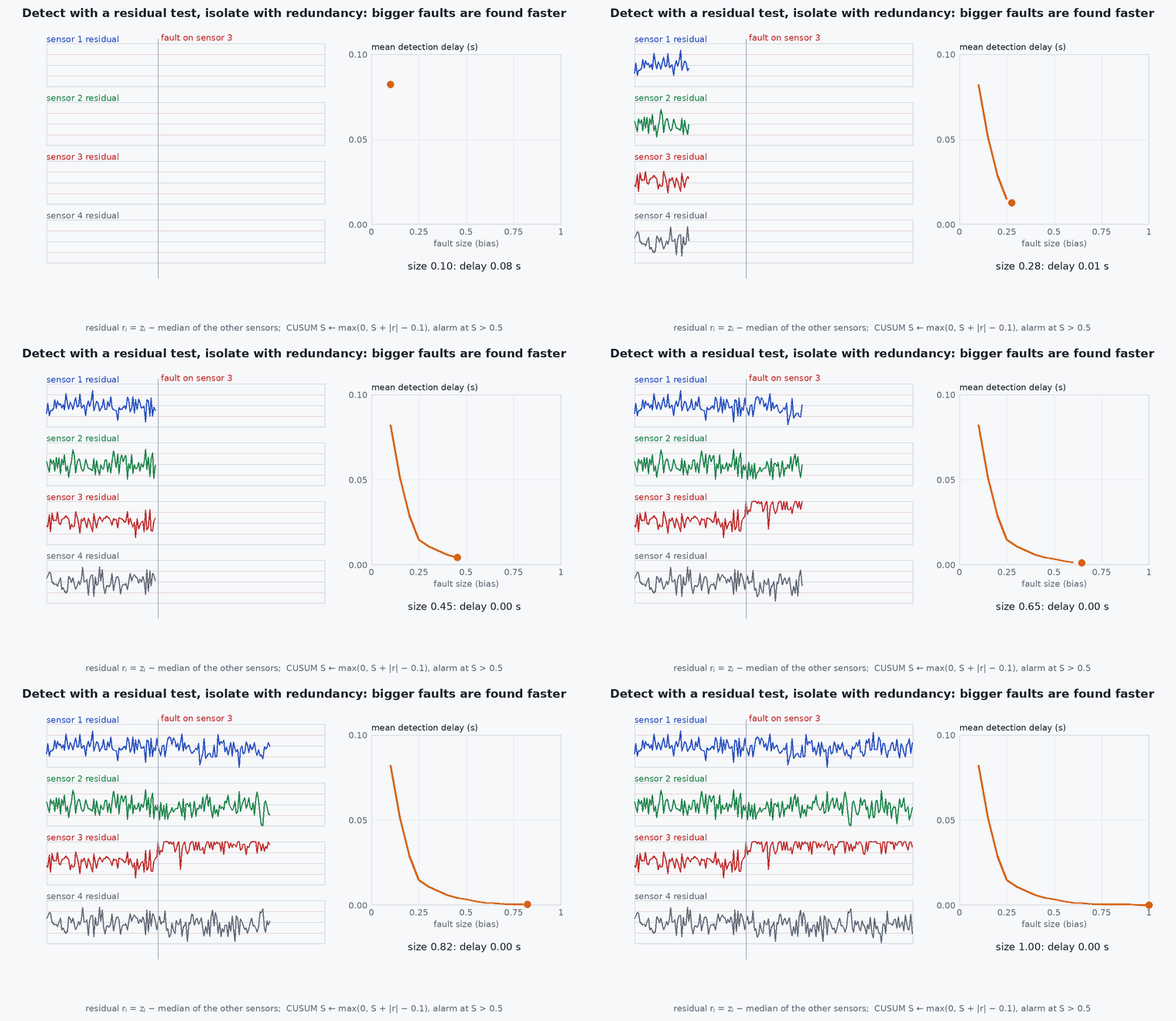
Typical UAV faults: stuck, bias step, drift ramp, increased noise, dropout, delayed data, scaling error. Different detectors suit different faults: a threshold catches large steps; CUSUM catches small persistent shifts; a variance test catches noise growth.
Engineering intuition
Two sensors that disagree tell you something is wrong but not which one: you need a third, or a model, to cast the deciding vote. With three, the odd one out is the faulty one if only one fails at a time. A single-fault assumption is therefore baked into most voting schemes: state it, and design what happens when two sensors fail.
Every detector trades two numbers. A lower threshold detects sooner but raises false alarms; a false alarm that excludes a healthy sensor is itself a fault. Choose the threshold from a false-alarm requirement (for example one per 100 flight hours) and then report the detection delay and the smallest detectable fault that result.
Mathematical formulation
Residuals from redundancy
CUSUM
For a shift of unknown sign and a reference (slack) and threshold in units of :
- slack, typically half the shift to be detected in units (0.5 detects a one-sigma shift well).
- decision threshold; larger lowers false alarms and lengthens delay.
The average detection delay after a shift (in ) is roughly samples when ; the average run length between false alarms grows roughly exponentially with . Both are standard results (Page 1954; Basseville and Nikiforov) and should be confirmed by simulation for your noise distribution.
Isolation by consistency
After detection, compare the pairwise differences averaged over a short window. Under a single fault, the two healthy sensors agree (|| small) and the faulty one disagrees with both. The faulty sensor is the one that is not in the best-agreeing pair.
Chi-square tests for vector residuals
For a measurement vector with innovation covariance , NIS = is chi-square (lesson M3-T14). A windowed NIS is the multivariate analogue of the CUSUM above.
Architecture and data flow
Each sensor stream → residual generator (model prediction or other sensors) → detector with a configured threshold → health record per sensor (valid, suspect, failed, with reason and time) → estimator (excludes or inflates the sensor) and navigation manager (confidence and mode, lesson M2-T16). Log every residual and every decision: the log is the evidence for the detection delay claimed in the FMEA (lesson M8-T7).
Real-world UAV applications
- Redundant IMUs and barometers on the flight controller.
- Cross-checking GNSS against odometry (lesson M2-T6).
- Rejecting a failed camera or LiDAR from a VIO and LIO estimator.
- Motor and ESC fault detection from current, rpm and expected response.
Implementation example
This runs as shown: three sensors measure the same signal; sensor gets a 5-sigma bias at . CUSUM detects it within a few samples without false alarms in the nominal period, and the pairwise-consistency rule isolates in every one of ten seeds.
import numpy as np

def cusum_first_alarm(r, kappa=0.5, h=8.0):
    sp = sm = 0.0
    for i, x in enumerate(r):
        sp = max(0.0, sp + x - kappa); sm = max(0.0, sm - x - kappa)
        if max(sp, sm) > h: return i
    return None

def run(seed, fault_at=300, bias=1.5, sigma=0.3, n=600):
    rng = np.random.default_rng(seed)
    t = np.arange(n) * 0.1; truth = 5 * np.sin(0.05 * t)
    z = truth[:, None] + sigma * rng.standard_normal((n, 3))
    z[fault_at:, 1] += bias                                         # sensor B develops a 5-sigma bias
    res = np.empty((n, 3))
    for j in range(3):
        others = [i for i in range(3) if i != j]
        res[:, j] = (z[:, j] - z[:, others].mean(axis=1)) / (sigma * np.sqrt(1.5))
    alarms = [cusum_first_alarm(res[:, j]) for j in range(3)]
    nominal_alarms = [cusum_first_alarm(res[:fault_at, j]) for j in range(3)]
    t_alarm = min(a for a in alarms if a is not None)
    w = slice(t_alarm - 5, t_alarm + 15)                            # short window around the alarm
    d = {(a, b): abs(np.mean(z[w, a] - z[w, b])) for a, b in [(0, 1), (0, 2), (1, 2)]}
    best_pair = min(d, key=d.get)                                   # the two sensors that agree best are healthy
    faulty = [j for j in range(3) if j not in best_pair][0]
    return t_alarm - fault_at, faulty, nominal_alarms

results = [run(s) for s in range(10)]
delays = [r[0] for r in results]
print("detection delay (samples):", delays, "| isolated sensors:", [r[1] for r in results])
assert all(r[2] == [None, None, None] for r in results)            # no false alarms in the healthy period
assert all(0 <= d <= 8 for d in delays) and all(r[1] == 1 for r in results)Common engineering mistakes
Setting thresholds by eye
Choose from a false-alarm requirement, then report the delay and minimum detectable fault.
Residuals contaminated by the faulty sensor
A residual against the mean of all sensors (including the faulty one) smears the fault across all residuals; use leave-one-out or a model.
Assuming single faults only without saying so
State the assumption and design the response to a second fault.
Detecting without a recovery action
A flag that nobody reads is not protection (lesson M8-T9).
Common-mode faults
Identical sensors with a shared dependency (power, vibration, clock) fail together and agree with each other while wrong; add diversity.
Failure modes
| Failure mode | How it shows up | Likely cause |
|---|---|---|
| False alarm | Healthy sensor excluded | Threshold too low for the real noise (non-Gaussian, heavy tails) |
| Missed slow drift | Fault grows below the detector’s sensitivity | Threshold or slack too large; drift slower than the detector can resolve |
| Wrong sensor isolated | Healthy sensor excluded, faulty one kept | Two simultaneous faults or correlated errors |
| Chattering | Sensor excluded and re-admitted repeatedly | No hysteresis on re-admission |
Debugging approach
- Replay recorded data with injected faults of each type and size and tabulate detection delay and misses.
- Plot residuals with the alarm thresholds drawn; check they look white and zero-mean in healthy data.
- Estimate the real false-alarm rate on many hours of healthy logs.
- Test isolation with every single-sensor fault and with a double fault.
Practical exercises
- Choose for an average run length between false alarms of 5000 samples and estimate the delay for a bias.
- Add a drift fault (ramp) instead of a bias and find the slowest ramp that is detected within 20 s.
- Extend the example to a stuck-at fault (sensor holds its last value).
- Use the GNSS-Denied Failure Simulator to inject a camera failure and read the detection time from the log.
Interview questions
Write an answer in your own words, then reveal the model answer. Nothing is sent anywhere.
Question 1
What is the difference between detection, isolation and recovery?
Model answer
Detection decides that a fault exists, isolation decides which element is faulty, recovery reconfigures the system (exclude, switch, degrade or stop) to remain safe.
Question 2
What does a CUSUM detect that a simple threshold does not?
Model answer
Small persistent shifts: it accumulates evidence over time so a bias well below the single-sample threshold is eventually caught.
Question 3
Why do you need at least three sensors for isolation by voting?
Model answer
With two, a disagreement cannot say which is wrong; the third provides the deciding comparison, assuming only one fault at a time.
References and further reading
Primary papers, official documentation and standards. Each claim above that is specific to a tool or version points here.
- . Basseville, I. . Nikiforov, Detection of Abrupt Changes: Theory and Application, Prentice Hall, 1993 (free online from the authors).
- E. S. Page, “Continuous inspection schemes”, Biometrika, 1954
- . Isermann, Fault-Diagnosis Systems, Springer, 2006.
- PX4: EKF2 innovation checks and sensor failure handling