UAV Systems Engineering · Module 2
M2-T12: Stereo visual odometry
A stereo pair measures depth directly, so motion comes out in metres without an IMU: at the price of a range limit set by the baseline.
Stereo removes monocular VO’s scale ambiguity by triangulating each feature with a known baseline. Understanding the depth error law tells you how to choose the baseline and the maximum range at which stereo is useful for a given vehicle and mission.
Learning objectives
After this lesson, you should be able to:
- Derive depth from disparity and the quadratic growth of depth error with range.
- Choose a baseline and focal length for a required range and accuracy.
- Estimate frame-to-frame motion from matched 3-D points by rigid alignment.
- Explain failure modes: textureless surfaces, calibration drift and distant scenes.
Conceptual explanation
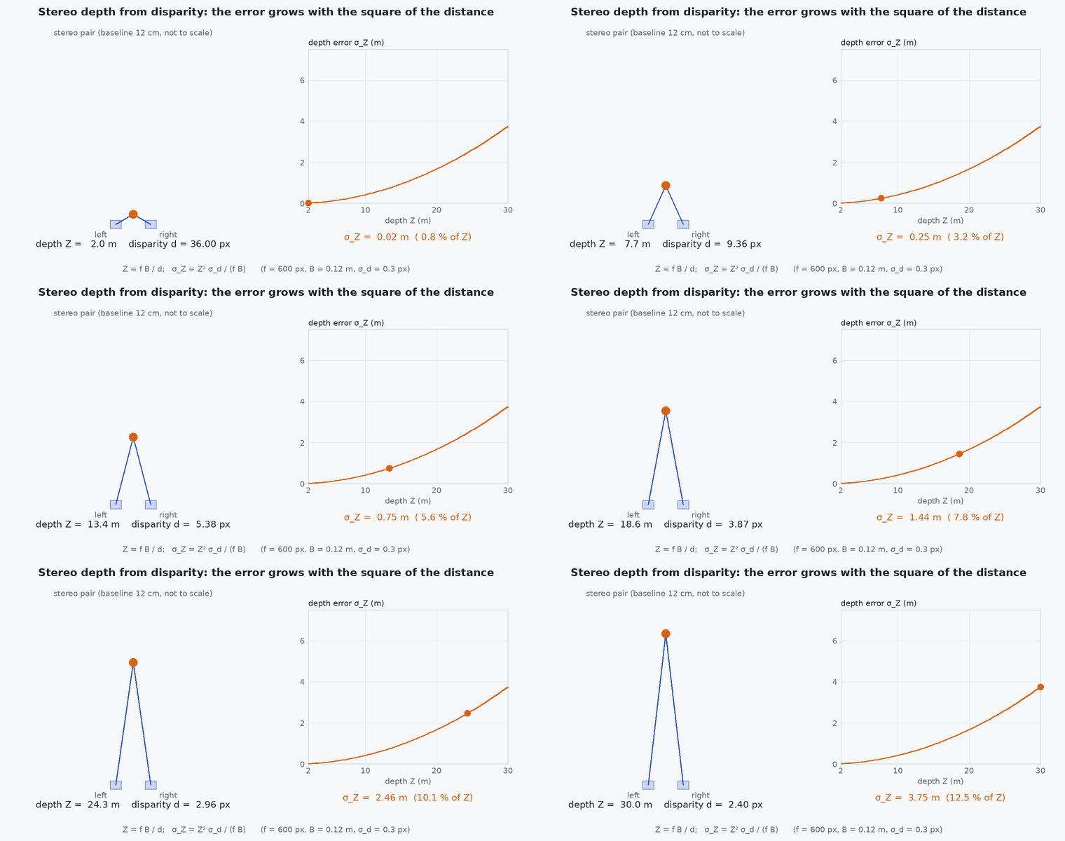
Two cameras separated by a baseline see a point at slightly different image positions; the horizontal difference is the disparity . After rectification, depth is . Triangulating the matched features at two consecutive times gives two 3-D point sets; the camera motion is the rigid transform that aligns them (3-D to 3-D), or the pose that explains the new image of the old 3-D points (PnP, 3-D to 2-D).
Engineering intuition
Depth resolution is fixed in disparity, not in depth: one pixel of disparity error is a small depth error up close and a large one far away, growing with the square of the distance. A 12 cm baseline camera with a 400 px focal length has useful depth to a few metres: beyond that, points carry almost no depth information and stereo behaves like monocular. A bigger baseline extends the range but makes close-range matching harder (less overlap) and needs stiffer mounting, because a flexing mount changes the calibration the whole method relies on.
Mathematical formulation
Depth and its error from disparity noise (pixels):
Given matched 3-D points (frame ) and (frame t+1), the rigid motion minimising the squared error is the Kabsch/Umeyama solution:
- focal length in pixels.
- baseline (m).
- disparity noise (typically a fraction of a pixel after sub-pixel matching).
Weight points by their depth uncertainty (far points count less) or discard points beyond a maximum range for a tolerated relative depth error precisely: .
Architecture and data flow
Hardware-synchronised stereo pair (a rolling-shutter or unsynchronised pair breaks the geometry) → rectification with calibration (lesson M7-T15) → disparity or feature matching → VO → odometry with covariance that reflects the depth uncertainty, together with the IMU in a VIO (lesson M2-T11). Stereo can feed obstacle mapping with the same disparity at no extra sensor cost.
Real-world UAV applications
- Metric VO without an IMU for short missions.
- Indoor obstacle avoidance and mapping.
- Providing scale to VIO initialisation.
- Landing site assessment.
Implementation example
This runs as shown: depth error against range for a given baseline; and a stereo VO step: 3-D points are triangulated before and after a known motion, with noise, and the motion is recovered by rigid alignment.
import numpy as np
rng = np.random.default_rng(4)
f, B, sigma_d = 400.0, 0.12, 0.3                                   # focal length (px), baseline (m), disparity noise (px)

depth_sigma = lambda Z: Z ** 2 / (f * B) * sigma_d
for Z in (1, 2, 5, 10, 20): print(f"Z = {Z:2d} m: depth sigma {depth_sigma(Z):.3f} m ({100 * depth_sigma(Z) / Z:.1f}%)")
assert abs(depth_sigma(10) / depth_sigma(5) - 4) < 1e-12 and abs(depth_sigma(5) - 25 / (f * B) * sigma_d) < 1e-12

def triangulate(P):                                                # points in the left camera frame (x right, y down, z forward)
    u = f * P[:, 0] / P[:, 2]; v = f * P[:, 1] / P[:, 2]; d = f * B / P[:, 2]
    u, v, d = (a + sigma_d * rng.standard_normal(len(P)) if a is d else a + 0.2 * rng.standard_normal(len(P)) for a in (u, v, d))   # pixel and disparity noise
    Z = f * B / d; return np.stack([u * Z / f, v * Z / f, Z], axis=1)

def kabsch(P, Q):
    Pc, Qc = P.mean(0), Q.mean(0); H = (P - Pc).T @ (Q - Qc); U, _, Vt = np.linalg.svd(H)
    R = Vt.T @ np.diag([1, 1, np.linalg.det(Vt.T @ U.T)]) @ U.T; return R, Qc - R @ Pc

th = np.radians(3.0); R_true = np.array([[np.cos(th), 0, np.sin(th)], [0, 1, 0], [-np.sin(th), 0, np.cos(th)]]); t_true = np.array([0.10, 0.0, 0.30])
X = np.stack([rng.uniform(-2, 2, 200), rng.uniform(-1.5, 1.5, 200), rng.uniform(2.0, 6.0, 200)], axis=1)       # points 2-6 m ahead
Xn = X @ R_true.T + t_true
P, Q = triangulate(X), triangulate(Xn)
R, t = kabsch(P, Q)
rot_err = np.degrees(np.arccos(np.clip((np.trace(R.T @ R_true) - 1) / 2, -1, 1)))
print(f"rotation error {rot_err:.2f} deg, translation error {np.linalg.norm(t - t_true) * 100:.1f} cm")
assert rot_err < 1.0 and np.linalg.norm(t - t_true) < 0.08Common engineering mistakes
Using far points as if they were accurate
Depth error grows with ; discard or down-weight them.
Unsynchronised stereo pair
Motion between exposures corrupts disparity: use hardware sync.
Mounting the cameras on a flexible bracket
The calibration drifts with vibration or temperature; use a rigid mount and re-check calibration.
Choosing the baseline from a datasheet photo
Compute the baseline from the required range and accuracy.
Ignoring rolling-shutter effects
Fast motion distorts geometry.
Failure modes
| Failure mode | How it shows up | Likely cause |
|---|---|---|
| Depth holes | Missing disparity on textureless surfaces | White walls, glass |
| Calibration drift | Systematic scale or rotation error | Mount deformation, temperature |
| Range limit | Distant scenes provide almost no depth | Baseline too small for the working range |
| Lighting changes | Auto-exposure differs between cameras | Unsynchronised exposure |
Debugging approach
- Verify the epipolar constraint on matched features after rectification: rows must match to sub-pixel.
- Check disparity statistics and holes.
- Compare stereo depth with a LiDAR or rangefinder at known distances.
- Re-run calibration after hard landings.
Practical exercises
- Choose for 5% depth error at 10 m with px and px.
- Add outliers to the example and use RANSAC around Kabsch.
- Compute the maximum range for 10% depth error with the example camera.
- Explain what happens to stereo VO when the scene is at 50 m (as for a high-altitude UAV).
Interview questions
Write an answer in your own words, then reveal the model answer. Nothing is sent anywhere.
Question 1
How does depth error scale with range in stereo?
Model answer
Quadratically: , so doubling the distance quadruples the depth error.
Question 2
How does stereo give metric scale?
Model answer
The known baseline between the cameras fixes the scale of triangulated points, so motion estimated from them is in metres.
Question 3
Why must the stereo cameras be synchronised and rigidly mounted?
Model answer
Disparity assumes both images capture the same instant and a fixed relative geometry; motion between exposures or flexing of the mount corrupts depth.
References and further reading
Primary papers, official documentation and standards. Each claim above that is specific to a tool or version points here.
- D. Scaramuzza, F. Fraundorfer, “Visual odometry [tutorial]”, IEEE RAM, 2011
- S. Umeyama, “Least-squares estimation of transformation parameters between two point patterns”, IEEE TPAMI, 1991
- OpenCV: depth map from stereo images
- . Hartley, A. Zisserman, Multiple View Geometry in Computer Vision, 2nd ed., Cambridge University Press, 2004.