UAV Systems Engineering · Module 5
M5-T1: UAV equations of motion
There is not one UAV model but a ladder of them: choose the simplest that is faithful to the question you are asking.
Planning, control design and simulation each need a different level of model. This lesson sets out the ladder from a 3-D point mass to a full rigid body with wind, shows how the frames and the airspeed triangle connect them, and states when each rung is appropriate.
Learning objectives
After this lesson, you should be able to:
- Write the kinematic and dynamic equations of a rigid-body UAV in the body and world frames.
- Relate ground velocity, airspeed and wind with the wind triangle.
- Select a model (point mass, planar, full rigid body) for planning, control and simulation.
- Compute heading and groundspeed for a wind-corrected flight with code.
Conceptual explanation
A rigid-body UAV has the translational and rotational equations of lesson M1-T5. Three simplifications are used in practice: a point-mass model with acceleration as input (for planning and outer-loop MPC), a planar model (altitude held, horizontal motion only), and the full rigid body with motor dynamics (for simulation and inner-loop design). Aerodynamic forces depend on the velocity relative to the air, so wind enters through the airspeed.
Engineering intuition
Each rung is valid when the dynamics it omits are much faster than the behaviour you care about. A planner thinking in seconds can treat the attitude loop as instantaneous (a point mass); a controller tuning the attitude loop at 20 rad/s cannot. And because lift and drag depend on airspeed, a wind of 5 m/s is not a small disturbance for a 10 m/s fixed-wing: groundspeed upwind may be half the airspeed, and the heading needed to track a line is no longer the line’s direction.
Mathematical formulation
Kinematics and dynamics in the world frame ( up), with body-to-world, world velocity, body rates, thrust , drag force as a function of airspeed :
1. Translation: where the vehicle goes
Why is the weight term negative?
The weight itself is not negative: its size is the positive number (for example 14.7 for a 1.5 kg vehicle). What carries the sign is its direction. In this lesson the world frame has pointing up, and is the unit vector along it. Gravity pulls down, opposite to ẑ, so the weight force vector is
Check it on the (vertical) component. The thrust, level, gives +T. The weight gives −mg. So . If > mg the vehicle climbs, if = mg it hovers, and if < mg it sinks. With a z-down frame such as NED, points down, so the same weight is written +mg and thrust is − : the physics is identical and only the sign convention changes. The same applies to drag, whose minus sign in −½ means “opposite to the airspeed”.
2. Rotation: how the vehicle points
3. Wind and drag
4. Putting it together
Reading each equation
| Equation | In words | What it tells you |
|---|---|---|
| Position changes at the rate of the velocity. | Definition of velocity. Position is the integral of velocity. | |
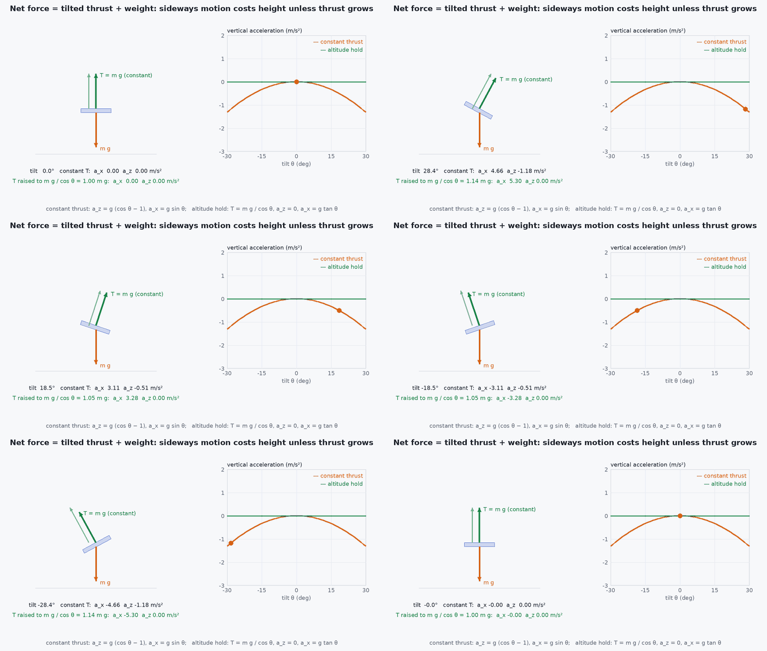
| Mass times acceleration equals the sum of the forces: thrust, weight and drag. | Thrust is along the body axis, so decides where it points. Tilt the vehicle and part of the thrust goes sideways: that is how it translates. | |
| The orientation changes at a rate set by the body angular velocity. | If the attitude is frozen. ₓ is the matrix that performs the cross product, ₓ a a. A rotation matrix has no gimbal lock, unlike Euler angles. | |
| Inertia times angular acceleration equals the applied torque minus the gyroscopic coupling. | Rotors produce by speeding up some motors and slowing others. The × J term is small for a symmetric vehicle at modest rates but matters in flips. | |
| Airspeed is the velocity relative to the moving air. | Hovering over the ground in a 5 m/s wind gives : the vehicle feels a 5 m/s headwind. | |
| Drag opposes the airspeed and grows with its square. | Doubling the airspeed quadruples the drag. Holding position in wind therefore needs a steady lean: . |
Symbols and units
| Symbol | Meaning | Frame | Unit |
|---|---|---|---|
| , | position, velocity | world | , m/s |
| , | mass, gravitational acceleration (about 9.81) | – | kg, |
| total thrust, the sum of the four rotor thrusts | along body | ||
| rotation matrix: turns body-frame vectors into world-frame vectors | – | – | |
| angular velocity (roll, pitch, yaw rates) | body | rad/s | |
| inertia matrix, nearly diagonal for a symmetric airframe | body | kg· | |
| torque produced by differential rotor thrust and rotor drag torque | body | · | |
| , | wind velocity, airspeed vector | world | m/s |
| , , A | air density (about at sea level), drag coefficient, reference area | – | kg/, –, |
Why the vehicle must tilt
The only force the rotors can create points along the body axis. A quadrotor has four inputs for six degrees of freedom, so it is underactuated: it cannot push sideways. The chain that results is
Torque changes the angular rate, the angular rate changes the attitude, the attitude redirects the thrust, and only then does the horizontal velocity change. That is why controllers are nested loops: a slow position loop asks for a tilt, a faster attitude loop tracks it, and a still faster rate loop commands torque.
Worked example: holding position in wind
Hovering with ground velocity in a steady 5 m/s wind gives an airspeed of 5 m/s. With illustrative values , , the drag is , pointing downwind. For a 1.5 kg vehicle the weight is 14.7 N, so the lean angle that balances it is , and the thrust rises to . At 15 m/s of wind the drag would be nine times larger, 13.5 N, and the lean angle about : the vehicle would be near the limit of its thrust and tilt margin. The numbers are illustrative; a real vehicle needs a measured drag coefficient.
What the equations leave out
The model is a rigid body with lumped drag. It omits motor and propeller lag (milliseconds), rotor drag in the rotor plane, ground effect, battery voltage sag and frame flexibility. These are accurate enough to ignore for moderate manoeuvres and matter for aggressive flight, high wind and system identification.
5. The wind triangle: which way to point
An aircraft moves through the air, and the air moves over the ground. The three velocities add like the sides of a triangle:
Let be the unit vector along the desired course and the unit vector to its left. Split the wind into a part along the course and a part across it:
The component of the airspeed across the course must cancel the crosswind, which gives the heading correction (the crab angle) and then the groundspeed:
Worked example. Fly due East at with a 5 m/s wind from the South, so pushes the vehicle North, to the left. Then and . The correction is : point to the right of the course, towards the wind. The groundspeed is , slightly less than the airspeed because part of it is spent fighting the crosswind. The code below reproduces these numbers.
- airspeed vector (velocity relative to the air).
- ,
- course (direction of ground velocity) and heading (direction the vehicle points).
- wind velocity.
The wind triangle has a solution only when ≥ the crosswind component: a vehicle slower than the crosswind cannot hold the track.
Architecture and data flow
The planner uses the point-mass model with limits derived from the rigid-body model (maximum horizontal acceleration ≈ , lesson M5-T8); the controller uses the linearised rigid body (lesson M5-T7); the simulator uses the full model with wind and noise. Keep the model parameters in one place so that all three agree (lesson M5-T2).
Control input, state, measurement and feedback
| Role | What it is | Examples |
|---|---|---|
| Control input | What the controller commands. | Physically the four motor speeds (ESC commands). In the equations they appear as the thrust and the three torques ; a mixer converts between them. |
| State | What the equations describe. | , , and : 12 numbers (3 position, 3 velocity, 3 attitude, 3 angular rate). |
| Measurement | What sensors give, with noise and bias. | Gyroscope: . Accelerometer: specific force (thrust plus drag over mass; not gravity or velocity). GNSS: position and velocity. Barometer: altitude. Magnetometer: heading. Camera, lidar, optical flow, rangefinder: motion relative to the surroundings. |
| Feedback | The estimated state compared with the setpoint. | The estimator (for example EKF2 in PX4) fuses the measurements into , , , . The controller acts on the error between the setpoint and this estimate. |
| Disturbance | An unmeasured input. | Wind (through the drag ), payload shifts, battery sag. Estimated by a disturbance observer or an EKF with wind states, not measured directly. |
In flight: hovering in calm air, the four motors run at nearly the same speed with and . To fly forward the controller speeds up the rear motors and slows the front ones, which produces a pitch torque; the vehicle pitches and the thrust acquires a forward component. To yaw it speeds up the motors that spin one way and slows the others. In a gust the airspeed and the drag change, the position and acceleration estimates show the push, and the controller leans into it. A controller can only be as good as its estimate, which is why the later modules on state estimation, visual-inertial navigation and fault detection exist.
Real-world UAV applications
- Choosing the model for MPC (point mass with acceleration limits).
- Wind-corrected waypoint tracking.
- Simulation fidelity decisions.
- Checking whether a vehicle can hold a track in forecast wind.
Implementation example
This runs as shown: a wind-triangle solver checked by reconstructing the ground velocity, the impossible-track case, and the energy effect of headwind on groundspeed.
import numpy as np

def wind_triangle(course_rad, airspeed, wind_xy):
    """Heading and groundspeed to track 'course' (angle of ground velocity from +x, ccw) in wind 'wind_xy' at 'airspeed'. None if the track cannot be held."""
    c = np.array([np.cos(course_rad), np.sin(course_rad)]); n = np.array([-c[1], c[0]])
    w_par, w_perp = wind_xy @ c, wind_xy @ n
    if abs(w_perp) > airspeed: return None
    delta = np.arcsin(-w_perp / airspeed)                           # wind correction angle
    heading = course_rad + delta
    ground = airspeed * np.cos(delta) + w_par
    return heading, ground

V = 15.0
for course_deg, wind in ((0, (0, 0)), (0, (-5, 0)), (0, (5, 0)), (0, (0, 5)), (90, (5, 0))):
    h, g = wind_triangle(np.radians(course_deg), V, np.array(wind, float))
    v_air = V * np.array([np.cos(h), np.sin(h)]); v_ground = v_air + np.array(wind)                 # reconstruct: airspeed + wind = ground velocity
    assert abs(np.degrees(np.arctan2(v_ground[1], v_ground[0])) - course_deg) < 1e-9 and abs(np.linalg.norm(v_ground) - g) < 1e-9
    print(f"course {course_deg:3d}, wind {wind}: heading {np.degrees(h):6.1f} deg, groundspeed {g:5.1f} m/s")
assert abs(wind_triangle(0.0, V, np.array([-5.0, 0.0]))[1] - 10.0) < 1e-9                 # a 5 m/s headwind removes 5 m/s of groundspeed
assert wind_triangle(0.0, 4.0, np.array([0.0, 6.0])) is None                              # crosswind stronger than the airspeed: the track cannot be held
assert abs(np.degrees(wind_triangle(0.0, V, np.array([0.0, 5.0]))[0]) + 19.47) < 0.01 # crab angle into a 5 m/s crosswind at 15 m/sCommon engineering mistakes
Planning in ground speed without wind
Energy, stall margin and control authority depend on airspeed.
Using a point-mass model beyond its bandwidth
Aggressive manoeuvres excite the attitude dynamics it ignores.
Frame confusion between body and world forces
Thrust is body-fixed, drag follows the airspeed vector.
Treating wind as zero-mean noise
It has a mean (and shear) that integral action or estimation must handle (lesson M5-T16).
Different parameters in planner, controller and simulator
Inconsistent models cause confusing behaviour.
Failure modes
| Failure mode | How it shows up | Likely cause |
|---|---|---|
| Cannot hold the track | Vehicle drifts downwind | Airspeed below the crosswind component |
| Planner infeasible trajectories | Tracker saturates | Point-mass limits above what the rigid body provides |
| Unmodelled drag at speed | Tracking error grows with speed | No drag term |
| Altitude loss in strong wind | Descent while tilting | Thrust margin consumed by tilt |
Debugging approach
- Compare the three models on the same input and see where they diverge.
- Fit a drag coefficient from a constant-speed log.
- Check that planner acceleration limits are inside the thrust envelope.
- Log wind estimates (if available) and airspeed.
Practical exercises
- Derive the maximum horizontal acceleration for a vehicle with at hover trim.
- Compute the heading and groundspeed for course , airspeed 12 m/s, wind (3, −4) m/s.
- Add a quadratic drag to the point-mass model and find the terminal speed for a given tilt.
- Decide the model for a 20 Hz MPC.
Interview questions
Write an answer in your own words, then reveal the model answer. Nothing is sent anywhere.
Question 1
What is a point-mass UAV model good for?
Model answer
Outer-loop planning and MPC where the attitude loop is fast compared with the manoeuvre: acceleration is treated as the input, limited by what the thrust and tilt permit.
Question 2
What is the wind correction angle?
Model answer
The angle between heading and course needed so that airspeed plus wind gives the desired ground track.
Question 3
Why does airspeed matter for a UAV?
Model answer
Aerodynamic forces and control authority depend on velocity relative to the air, not the ground.
References and further reading
Primary papers, official documentation and standards. Each claim above that is specific to a tool or version points here.
- R. Mahony, V. Kumar, P. Corke, IEEE RAM 2012
- . . Beard, . . McLain, Small Unmanned Aircraft: Theory and Practice, Princeton University Press, 2012: the chapter on coordinate frames has the section on airspeed, wind speed and ground speed (the wind triangle and the course and heading angles used here).
- T. Lee, M. Leok, N. H. McClamroch, “Geometric tracking control of a quadrotor UAV on SE(3)”, IEEE CDC, 2010 (uses and ₓ as written here)
- K. M. Lynch, F. C. Park, Modern Robotics: Mechanics, Planning, and Control (free online edition): rotation matrices, angular velocity, rigid-body dynamics
- PX4: controller diagrams (the nested position, attitude and rate loops)
- ROS REP-103: coordinate frame conventions
- FAA: Pilot’s Handbook of Aeronautical Knowledge (the chapter on navigation explains the wind triangle, wind correction angle and groundspeed in plain language)
- . . Stevens, . . Lewis, . . Johnson, Aircraft Control and Simulation, 3rd ed., Wiley, 2015.