UAV Systems Engineering · Module 2
M2-T9: Vision-aided navigation
A camera turns the world into a reference: it observes motion relative to the scene, which the IMU cannot, and it fails whenever the scene gives it nothing to hold on to.
Vision-aided navigation is the first step beyond inertial dead reckoning without GNSS. The principle is simple: measure how the image changes and convert that to motion. The engineering is knowing what scale information you have and what lighting and texture you need.
Learning objectives
After this lesson, you should be able to:
- Distinguish relative vision measurements (optical flow, odometry) from absolute ones (landmarks, maps).
- Compute velocity from optical flow with gyro derotation and a known height.
- State what vision observes and what remains unobservable.
- List the environmental conditions that defeat vision-aided navigation.
Conceptual explanation
Cameras provide two kinds of aiding. Relative measurements describe motion between frames: optical flow (image motion per second) gives velocity if the depth is known; visual odometry gives relative pose (lesson M2-T10). Absolute measurements tie the vehicle to a map: recognised landmarks, fiducial markers, or matching to a prior map or orthophoto give position without drift.
Engineering intuition
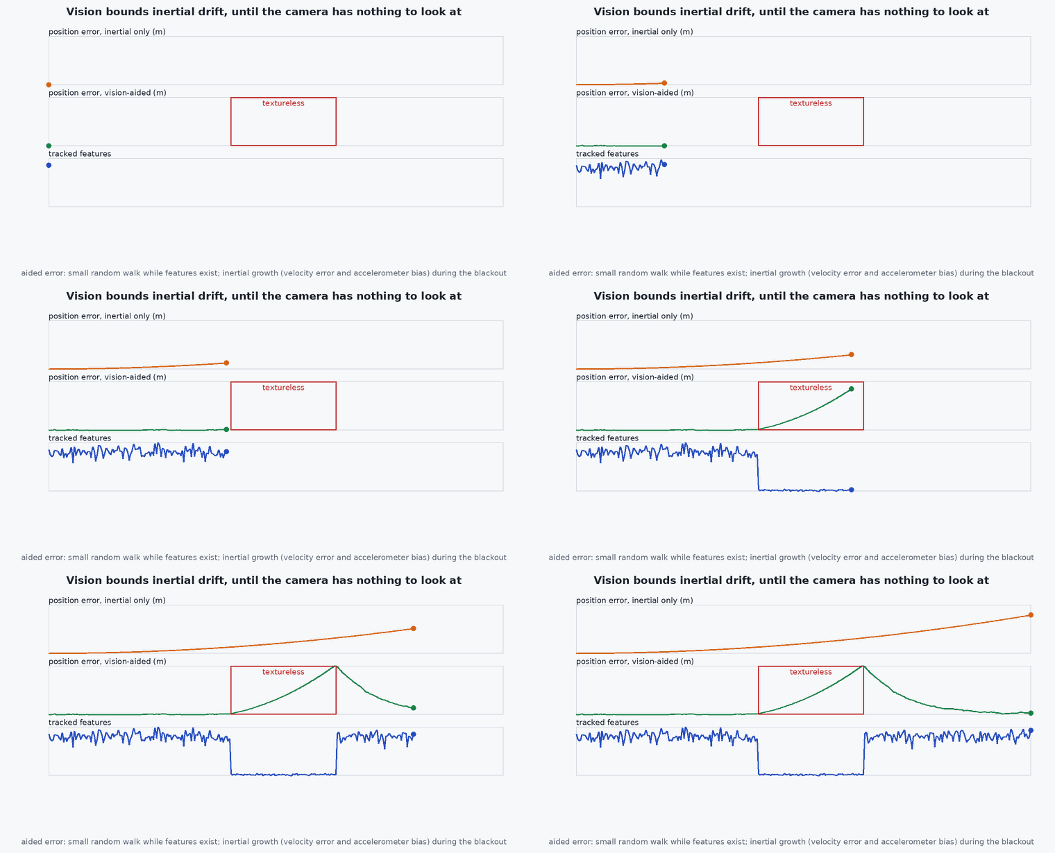
Inertial dead reckoning loses velocity quickly because it integrates a biased acceleration. A downward camera sees the ground move; if you know the height, the speed is the image motion times height over focal length, regardless of the accelerometer bias: velocity error is bounded and position error then grows linearly with distance instead of quadratically with time. What the camera does not give is scale from a single view (you need height, stereo or inertial information) or any global position without a map.
It also needs light and texture: low light, motion blur, uniform surfaces (water, snow, white walls), repeated patterns and dynamic scenes remove the information it relies on (lesson M2-T10).
Mathematical formulation
For a downward-looking camera at height with focal length (pixels), translating at ground velocity and rotating at body rate , the optical flow (pixel per second) is:
The rotation term must be removed using the gyro (derotation): otherwise a tilt of 10°/s looks like a velocity of ·0.17 m/s, which at 5 m height is 0.9 m/s. The velocity error depends on the height error and the flow noise:
- height above the textured surface (m): from a rangefinder or barometer; a height error scales velocity proportionally.
- focal length in pixels.
- angular rate about the axis perpendicular to the motion (rad/s).
Architecture and data flow
Camera → feature tracker → flow field → robust average (reject outliers) → derotate with gyro → scale with height → velocity measurement with covariance → estimator (EKF2 supports optical flow input with a height source; check the PX4 optical flow documentation for the topic and parameters). Quality indicators (feature count, flow consistency) must travel with the measurement.
Real-world UAV applications
- Position hold indoors with a downward camera and rangefinder.
- Landing on a marker.
- Supplementing VIO with a simple, robust velocity.
- Drift bounding when GNSS fails.
Implementation example
This runs as shown: a flow-to-velocity estimator with derotation and a check of the error budget by Monte Carlo.
import numpy as np
rng = np.random.default_rng(1)
f = 400.0                                                        # focal length in pixels

def flow_measurement(v, h, omega, sigma_flow):                   # pixels per second, one axis
    return f * (v / h) + f * omega + sigma_flow * rng.standard_normal(np.shape(v))

def velocity_from_flow(flow, h, omega): return h * (flow / f - omega)

v_true, h, omega = 3.0, 5.0, np.radians(10.0)                    # 3 m/s at 5 m height while pitching at 10 deg/s
flow = flow_measurement(np.full(10000, v_true), h, omega, 4.0)
naive = velocity_from_flow(flow, h, 0.0); derot = velocity_from_flow(flow, h, omega)
print(f"naive v = {naive.mean():.2f} m/s, derotated v = {derot.mean():.2f} m/s (true {v_true})")
assert abs(derot.mean() - v_true) < 0.02 and abs(naive.mean() - v_true) > 0.8              # ignoring rotation gives a velocity error h*omega = 0.87 m/s

# error budget: height error of 5% and noise
h_est = h * (1 + 0.05 * rng.standard_normal(10000)); sig = np.std(velocity_from_flow(flow, h_est, omega))
sigma_pred = np.sqrt((0.05 * v_true) ** 2 + (h / f * 4.0) ** 2)
print(f"std {sig:.3f} m/s, predicted {sigma_pred:.3f}")
assert abs(sig - sigma_pred) / sigma_pred < 0.15Common engineering mistakes
Omitting derotation
Rotation looks like translation: large errors during attitude changes.
Trusting the height source blindly
A rangefinder over a slope or water breaks the scale.
Averaging all flow vectors
Moving objects and outliers bias the mean; use robust statistics.
No quality indicator
The estimator cannot lower the weight on bad scenes.
Testing only on textured floors
Real sites include shiny, uniform or repetitive surfaces.
Failure modes
| Failure mode | How it shows up | Likely cause |
|---|---|---|
| Drift over featureless surface | Estimated velocity near zero while moving | No texture: flow estimator returns noise or zero |
| Oscillation during aggressive attitude change | Position wobble | Derotation delay or missing |
| Scale error | Velocity proportional to height error | Wrong height source |
| Failure in low light | Tracking lost at dusk | Exposure limits, noise |
Debugging approach
- Plot flow-derived velocity against another source (GNSS or motion capture).
- Check the derotation sign by yawing and pitching in place.
- Log feature count and flow quality with each measurement.
- Verify the height source against a tape measure.
Practical exercises
- Compute the velocity error from a 2 cm timing offset between gyro and flow at 20°/s and 4 m height.
- Estimate the minimum texture (features per frame) required for 5% velocity noise.
- Describe the behaviour you want from the estimator when flow quality drops.
- Find the PX4 optical flow documentation and list its required inputs.
Interview questions
Write an answer in your own words, then reveal the model answer. Nothing is sent anywhere.
Question 1
What does optical flow measure and what do you need to turn it into velocity?
Model answer
Image motion in pixels per second; velocity needs the height above the surface and removal of rotation using gyro rates.
Question 2
Why does vision aiding bound drift?
Model answer
It observes motion relative to the scene, giving velocity without accelerometer bias, so position error grows linearly with distance instead of quadratically with time.
Question 3
What defeats vision-aided navigation?
Model answer
Low light, blur, uniform or repetitive surfaces, dynamic scenes and wrong scale (height) information.
References and further reading
Primary papers, official documentation and standards. Each claim above that is specific to a tool or version points here.