UAV Systems Engineering · Module 5
M5-T10: Waypoint navigation
Following a list of points sounds trivial until the vehicle cuts corners, overshoots turns or never quite “arrives”. The guidance law and the acceptance rule decide all three.
A mission is a list of waypoints, but the vehicle flies legs between them. How the autopilot decides it has reached a waypoint, and what it steers toward in between, determines accuracy, smoothness and failure behaviour. These choices are simple, and a surprising number of field problems come from leaving them at defaults.
Learning objectives
After this lesson, you should be able to:
- Define a leg, cross-track error and along-track distance from two waypoints.
- Choose acceptance radius and speed at waypoints from vehicle dynamics and mission requirements.
- Implement a carrot (look-ahead) guidance law and explain its tuning parameter.
- List the safety conditions a waypoint mission must monitor.
Conceptual explanation
Established Line-of-sight and carrot guidance are standard textbook methods. Specific autopilot behaviour (acceptance radius parameters, corner blending, speed limits) is implementation-specific: read the documentation of your autopilot.
A waypoint mission is an ordered list of positions (and optionally altitude, speed, yaw and hold time). Between waypoints and the vehicle flies a leg. Two ideas matter:
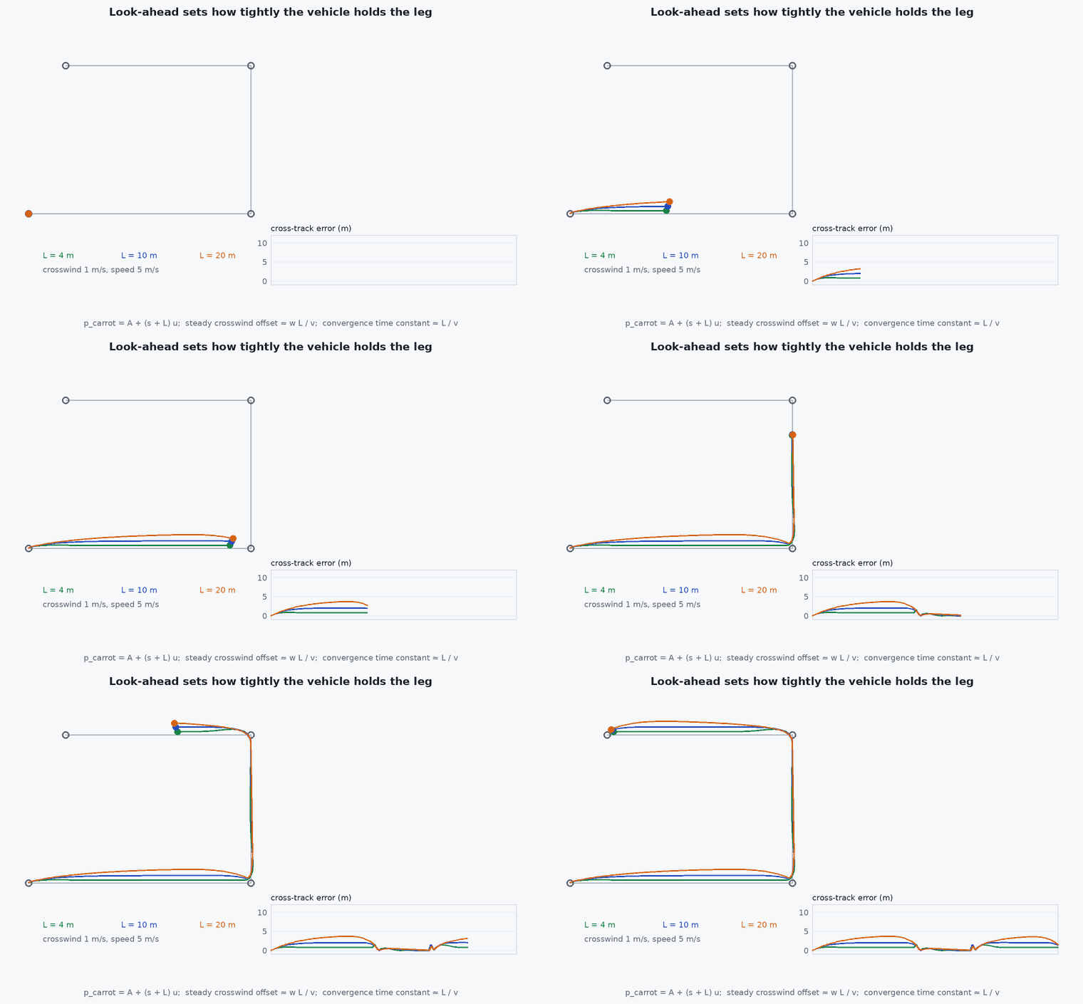
- Guidance: what point or velocity to command at each instant. Flying directly at the next waypoint (pure pursuit of the waypoint) is simple, but a gust that pushes the vehicle off the line leaves it on a curved path. Flying toward a point on the leg a look-ahead distance ahead of the vehicle’s projection (carrot or line-of-sight) holds the line.
- Acceptance: the condition that advances to the next waypoint. A radius that is too small means the vehicle circles or stalls; too large and corners are cut.
Engineering intuition
Imagine leading a dog with a treat held ahead of it along a rope. A short rope (small look-ahead) makes the dog hug the line but jerk around; a long rope makes it smooth but lets it cut corners. The look-ahead distance is the single most important tuning knob, and it should scale with speed: at 10 m/s a 2 m look-ahead is asking for oscillation, because the vehicle crosses it in 0.2 s.
Acceptance is the same trade-off in time. The vehicle is a physical object with lag; it cannot turn instantly. If you require it to be within 0.2 m of a waypoint before turning, it must decelerate to nearly zero first. If you accept within 3 m, it turns early and flies a rounded corner at speed. Neither is wrong: the mission requirement (photograph the target? pass a gate? survey a field?) decides.
Mathematical formulation
For a leg from A to with unit direction and vehicle position , define the projection and the errors:
A velocity command toward the carrot with speed is . The geometry gives the cross-track dynamics for small errors: with speed the cross-track error decays with time constant about L/v, so
Choosing for the desired time constant (say 2–4 s for a smooth multirotor, depending on its limits) makes scale with speed. Corner speed is limited by the available lateral acceleration : for a turn of radius , , and a corner of interior angle blended with acceptance radius has a radius of roughly -type geometry (the exact relation depends on the blending method).
- ,
- leg end points (m).
- look-ahead distance (m).
- cross-track error (m).
- maximum lateral acceleration the vehicle can sustain .
Architecture and data flow
Mission item list (from the ground station or the companion computer) → navigator (current leg, acceptance logic) → position/velocity setpoint → position controller → attitude controller. In PX4 the navigator publishes a position setpoint triplet (previous, current and next) that the position controller uses to blend corners; in ArduPilot the equivalent is the waypoint navigation controller with its own acceptance radius and spline options. The safety monitors (geofence, battery, link and estimator status) sit beside the navigator and can override it with return or land.
Real-world UAV applications
- Survey and mapping missions flown as lawn-mower legs.
- Inspection routes along infrastructure.
- Automated delivery and patrol routes.
- Test routines in SITL: the same mission replayed with different wind and sensor noise.
Implementation example
This runs as shown. A point-mass vehicle with a first-order velocity response (time constant 0.5 s, a stand-in for the inner loops) and a steady crosswind flies a 3-waypoint mission with carrot guidance. A pure carrot law has no wind feedforward, so the crosswind leaves a steady cross-track offset of about / (here 1 × 10 / 5 = 2 m); the test confirms the simulated offset matches that prediction and that the mission completes. Reducing the offset needs integral action on cross-track error or a wind estimate.
import numpy as np

def carrot(p, A, B, L):
    u = (B - A) / np.linalg.norm(B - A); s = u @ (p - A)
    n = np.array([-u[1], u[0]]); e_ct = n @ (p - A)
    return A + (s + L) * u, s, e_ct, np.linalg.norm(B - A)

W = [np.array(w, float) for w in [(0, 0), (60, 0), (60, 40)]]
dt, tau_v, v_cmd, R_acc = 0.05, 0.5, 5.0, 2.0
wind = np.array([0.0, 1.0])                           # 1 m/s steady crosswind pushes the vehicle off the first leg
p = W[0].copy(); v = np.zeros(2); leg = 0; worst = 0.0; t = 0.0
while leg < len(W) - 1 and t < 120:
    A, B = W[leg], W[leg + 1]
    c, s, e, length = carrot(p, A, B, L=v_cmd * 2.0)    # look-ahead = speed x 2 s
    c = A + (B - A) * min(1.0, max(0.0, (c - A) @ (B - A) / length ** 2))   # never aim past the waypoint
    dirn = (c - p) / max(np.linalg.norm(c - p), 1e-6)
    v += (v_cmd * dirn - v) / tau_v * dt                # first-order velocity response
    p += (v + wind) * dt; t += dt
    if t > 8.0 and leg == 0: worst = max(worst, abs(e))     # after the transient
    if np.linalg.norm(B - p) < R_acc: leg += 1
print(f"mission complete: {leg == len(W) - 1}, time {t:.1f} s, worst cross-track {worst:.2f} m on leg 1")
print(f"predicted steady offset w L / v = {1.0 * 10.0 / 5.0:.2f} m")
assert leg == len(W) - 1 and 1.5 < worst < 2.5Common engineering mistakes
Fixed look-ahead at all speeds
It becomes too short at high speed and oscillates; scale with speed.
Acceptance radius smaller than the position error
The vehicle never “arrives” and hovers forever; the radius must exceed the achievable position accuracy including GNSS or VIO error.
Ignoring the leg beyond the waypoint
The carrot can pass the waypoint and pull the vehicle past it: clamp the projection.
Altitude and horizontal legs treated identically
Climb rates and horizontal speeds have different limits.
No mission-level timeout
A stalled waypoint can hold the vehicle until the battery is empty.
Failure modes
| Failure mode | How it shows up | Likely cause |
|---|---|---|
| Corner cutting | Vehicle passes far from the waypoint | Acceptance radius too large or no corner speed limit |
| Hovering at the waypoint forever | Never advances | Radius smaller than position error; wrong waypoint frame or altitude reference |
| Snaking along the leg | Oscillation around the line | Look-ahead too short for the speed and inner-loop lag |
| Wide arcs in wind | Large cross-track error | Pure pursuit of the waypoint instead of line following; wind exceeds capability |
Debugging approach
- Plot the flown path over the planned legs and the cross-track error against time.
- Log the acceptance distance at each waypoint switch.
- Replay the mission in SITL with wind off, then on, to separate guidance faults from estimation faults.
- Check the frame and altitude reference (relative to home, above mean sea level) for each waypoint.
Practical exercises
- Change the look-ahead to 0.5 s × speed and 6 s × speed and compare cross-track error and corner cutting.
- Add a corner speed limit with and a radius derived from the acceptance circle.
- Add integral action on cross-track error (or a wind-velocity feedforward) and show the steady offset going to zero.
- Write the acceptance logic for a waypoint that requires a 5 s hold and a heading.
Interview questions
Write an answer in your own words, then reveal the model answer. Nothing is sent anywhere.
Question 1
What is cross-track error and how is it used in guidance?
Model answer
The signed perpendicular distance from the planned leg. Guidance laws such as carrot or line-of-sight steer to reduce it with a time constant set by the look-ahead distance divided by speed.
Question 2
How do you choose a waypoint acceptance radius?
Model answer
Larger than the achievable position accuracy (so the vehicle can arrive) and smaller than the mission tolerance. Trade corner speed against precision: tight acceptance forces slow, near-stopped corners.
Question 3
Why scale the look-ahead with speed?
Model answer
The cross-track time constant is L/v. A fixed makes the loop faster as speed rises, until the vehicle’s inner-loop lag makes it oscillate.
References and further reading
Primary papers, official documentation and standards. Each claim above that is specific to a tool or version points here.